Siemens LLM-1 Leased Line Module, Installation Instructions

File Preview
Click below to download for free
Click below to download for free
File Data
| Name | siemens-llm-1-leased-line-module-installation-instructions-0428697351.pdf |
|---|---|
| Type | |
| Size | 779.90 KB |
| Downloads |
Text Preview
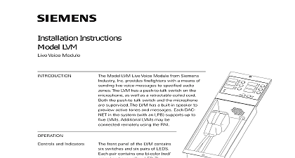
Installation Instructions LLM 1 Line Module Model LLM 1 Leased Line Module from Industry Inc provides telephone equip overvoltage suppression in compliance with The LLM 1 must be used with the follow equipment System MXL CSM 4 RCM 1 System 3 LP 30 MT 30 NCC WAN MXL XL3 WAIO FS 250 FS DACT MPC 6000 MPC 7000 RND 2 MPC FireFinder XLS ZIC 4A all power before installation first and then AC power up connect the AC first and then the provide overvoltage protection in the event that lines come in contact with the leased tele line the LLM 1 must be connected in series the leased line prior to entry in each panel the LLM 1 assembly to the inside surface of enclosure in a practical location Center the on the side wall of the enclosure using a mechanical fastener to Figures 1 12 wiring must comply with national and local Industry Inc Technologies Division Park NJ 315 093530 7 The total loop resistance from the LLM 1 to a Tie including the 14.5 ohms in the Tie should not exceed 22.5 ohms To reduce the risk of fire use only No 26 or larger telecommunication line cord MXL Use the LLM 1 with the CSM 4 for Leased Line Figure 1 and Municipal Tie 2 applications Connect the LLM 1 to the for transient protection UL 1459 whenever copper wire pair leaves the building Campus Note that in Style 4 connections LLM 1s are required Figures 3 and 5 and in 7 connections four LLM 1s are required 4 3 Use the LLM 1 with the LP 30 for Line connection Figure 6 and with the for Municipal Tie connection Figure 7 WAN Use the LLM 1 with the HUB 4 for Line connection Refer to the HUB 4 Instructions P N 315 099458 for wiring connections to MXL XL3 or WAIO Use the LLM 1 with the FS DACT for connection Figure 10 Use the LLM 1 the MPC DACT for telephone connection 10 XLS Use the LLM 1 with the ZIC 4A for Leased Line Figure 11 and Municipal Figure 12 applications Refer to the ZIC 4A Instructions P N 315 033050 for more Ratings Canada Limited Technologies Division Kenview Boulevard Ontario L6T 5E4 Canada SHOWN IN NORMAL STATE LEASED LINE CIRCUITS ARE POWER LIMITED PER NEC 760 RESISTANCE 2K 5K OHMS 1 Leased Line Circuit SHOWN IN SUPERVISORY STATE CIRCUIT MAY BE USED MUNICIPAL TIE CIRCUITS ARE POWER LIMITED PER NEC 760 The total loop resistance from the LLM 1 the Municipal Tie including the 14.5 in the Municipal Tie should not 22.5 ohms 2 Loop Wiring of Supervised Tie Local Energy Trip USE 2 WIRE COPPER CABLE 105OC 18 AWG SOLID OR STRANDED 7 STRANDS 3 the LLM 1 to the RCM 1 Style 4 Connection Riser 4 the LLM 1 to the RCM 1 Style 7 Connection C Global Riser USE 2 WIRE COPPER CABLE 105OF 18 AWG SOLID OR STRANDED 7 STRANDS the LLM 1 to the RCM 1 Style 4 Connection Global Riser Output Only 5 6 the LLM 1 to the LP 30 7 the LLM 1 to the MT 30 OHMS EOLR OR INTERFACE 2 ADDITIONAL MAX 16 LAST WITH 120 OHM ON 3 4 NEXT Mount the LLM 1 within the monitored fire panel enclosure Positive or negative ground fault detected at 25K ohms on pins 1 16 200 ohms max per pair max line to line OR OR INTERFACE 3 INTERFACE 4 SLOT OF CC 2 5 HUB 4 INSTALLED PSC 12 TB4 PSC 12 TB4 Class B Style 4 Wiring to WAIO Connection 8 ADDITIONAL MAX 16 LAST WITH 120 RESISTOR TERMINALS 4 AND 5 6 NEXT OR INTERFACE 2 OR OR INTERFACE 3 INTERFACE 4 SLOT OF CC 2 5 HUB 4 INSTALLED PSC 12 TB4 PSC 12 TB4 Mount the LLM 1 within the monitored fire panel Refer to the LLM 1 Installation Instructions P 315 093530 for further information Positive or negative ground fault detected at 25K ohms CC 5 pins 1 16 200 ohms max per pair max line to line Class A Style 7 Wiring to WAIO Connection 9 Output to telephone The DACT may seize line to report events Output to telephone The DACT may seize line to report events 24VDC nominal 0.054A max Equivalence 0.4B Line 1 from TELCO Line 2 from TELCO for LLM 1 and FS 250 with FS DACT and MPC 6000 or RND 2 with MPC DACT 10 1 All wiring must be in with 760 of NEC local building codes 2 All output circuits are power limited 3 Electrical Ratings Coil 14.5 ohms Current to 320mA DC Current DC 24V nominal 4 EOL resistor 24k ohms watt 5 P N 140 820405 5 Polarity shown in active state 6 Supervised for open circuit only 7 LLM 1 module is required The total resistance from the LLM 1 to Municipal Tie including the ohms in the Municipal Tie not exceed 22.5 ohms 8 Wire jumper must be connected the positive terminals the output 9 Any circuit may be used Minimum Emergency Power hours standby minute alarm Refer to CAB1 CAB1R P N 315 0330007 and CAB2 BB CAB3 BB 315 033009 Installation Instructions for details on the separation of limited and non power limited wiring Positive or negative ground fault detected at 40K ohms for terminals 1 16 Supervised Municipal Tie Wiring 11 1 NOT USE NOT USE SLOT OF CC 5 1 2 3 4 3 1 2 4