Siemens MKB-1 Annunciator Keypad Module, Installation Instructions

File Preview
Click below to download for free
Click below to download for free
File Data
| Name | siemens-mkb-1-annunciator-keypad-module-installation-instructions-0412673598.pdf |
|---|---|
| Type | |
| Size | 679.68 KB |
| Downloads |
Text Preview
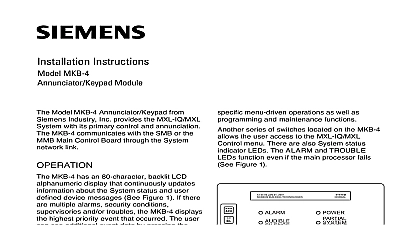
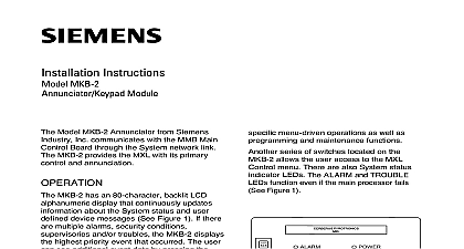
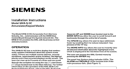
Installation Instructions MKB 1 Module Model MKB 1 Annunciator from Siemens Inc communicates with the MMB Main Board through the System network link MKB 1 provides the MXL with its primary and annunciation MKB 1 has an 80 character backlit LCD display that continuously updates about the System status and user device messages See Figure 1 If there multiple alarms security conditions and or troubles the MKB 1 the highest priority event that occurred user can see additional event data by the NEXT key Press the HOLD key at time to stop the display from scrolling are switches for acknowledging fire alarms ACK silencing audibles AUD SIL supervisories SUPV ACK troubles TRBL ACK and security SEC ACK There is also a separate for resetting the Control Panel RESET 10 digit numeric keypad allows entry of the levels of user passwords It also performs menu driven operations as well as and maintenance functions series of switches located on the MKB 1 the user access to the MXL Control menu are also System status indicator LEDs The and TROUBLE LEDs function even if the processor fails See Figure 1 Industry Inc Technologies Division Park NJ 315 090856 9 all system power before installation battery and then AC To power up the AC first then the battery the MKB 1 Inspect the module for such as integrated circuits ICs not firmly in their sockets bent IC pins connectors properly installed dirt and packing material the board the Network Address Figure 2 Before installing the MKB 1 panel set the address on S1 the switch on the board located on the back of the Use dipswitches SW1 and SW2 on Sl to set the network address of the The MKB 1 module address is always set network addresses 248 through 251 the individual switches as follows Switches S1 SW3 and S1 SW4 are for use The use of switch S1 SW5 is below One supervised MKB 1 must be installed at address 251 Other supervised may be at the other addresses Building Technologies Ltd Safety Security Products Kenview Boulevard Ontario 5E4 Canada Select Supervision Installation Switch S1 SW5 on the ANN 1 to select or supervision of the MKB 1 If your ANN 1 a switch with position 1 indicated on the side ignore the printing on the switch on S1 is at the extreme right hand side of regardless of any other marking set for supervision Closed ON set for non supervision Open OFF supervision is independent of the network installation kit for the MKB 1 includes nuts 2 inch standoffs Mount the MKB 1 inside the main MXL by placing the four holes in the bracket over the four studs provided the enclosure These studs are placed two and two below the MMB 1 board See 2 the MKB 1 is in position it straddles the of the MMB 1 leaving only the field terminals on the MMB 1 exposed Fasten the MKB 1 bracket in the enclosure the two 2 inch standoffs provided on top the two nuts provided at the bottom Once the MKB 1 is mounted to the enclosure the cable assembly on the back of the to connector P8 on the MMB 1 1 Panel 2 S1 on the ANN 1 Board RATINGS 315 090856 9 the MKB 1 Module in the Enclosure 3