Siemens MLE-6 Installation and Power Limited Wiring Instructions

File Preview
Click below to download for free
Click below to download for free
File Data
| Name | siemens-mle-6-installation-and-power-limited-wiring-instructions-3240916578.pdf |
|---|---|
| Type | |
| Size | 643.88 KB |
| Downloads |
Text Preview
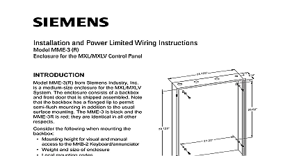
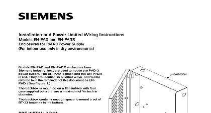
Installation and Power Limited Wiring Instructions MLE 6 for the MXL MXLV Control Panel MLE 6 from Siemens Industry Inc is a enclosure for the MXL MXLV System enclosure consists of a backbox and front that is shipped assembled Note that the has a flanged lip to permit semi flush in addition to the usual surface the following when mounting the Mounting height for visual and manual to the MKB 2 Keyboard annunciator Weight and size of enclosure Local mounting codes the backbox securely to a clean dry and vibration free surface MLE 6 is for indoor use only in dry environ Position the backbox clear of obstruc so that the front door opens freely and so the indicators and controls are easily When the backbox is mounted semi be sure that the position of the permits the front door to fully open install the MLE 6 backbox to Figure 1 Slip the front door off the hinges of the box put it to one side temporarily 1 the Backbox Hold the empty backbox against the wall at a that provides easy access Mark drill points on the wall in the center of the slots on the upper rear of the backbox Drill the two holes and screw in the top bolts a gap between the wall and the rear each bolt head Mount the backbox on the two bolts and then the bottom bolts in the two holes provided Tighten all bolts securely against the back of the backbox Remove the knockouts in the backbox Slip the front door back on the hinges of the field wiring is required See Figure 2 Industry Inc Technologies Division Park NJ 315 094970 5 Building Technologies Ltd Safety Security Kenview Boulevard Ontario 5E4 Canada Door 2 the Front Door DOOR front door is the main outer door for the enclosure The door is supplied filler plates for the three large To select the appropriate filler for the three openings follow the below When visual indication of system LCD LED or printer is install clear panels the MDL 1 behind the appropriate door When visual indication of the system is not required install plain panels MDB 1s behind the door openings When audio amplifiers such as the or ZAC 30 are used the MDG 1 MXL Door Venting behind the appropriate door After determining which filler plates required insert the appropriate in the front door as shown in 3 using the hardware supplied the Filler Plates in the Front Door 3 PLATES and MBR 3MP the MBR MP and MBR 3MP Mounting Plates are shipped separately Refer to the MBR MP Installation Instructions P N 315 094882 compliance with UL 864 effective May 1 1995 power limited fire protective signaling conduc must be separated a minimum of 1 4 inch from of the following items located within a control electric light power Class 1 or non power limited fire protective conductors meet the above requirements the following must be observed when installing and wiring to this control panel If power limited wiring is not used within MXL MXLV enclosure then the follow guidelines do not apply In that case sure to follow standard wiring practices ENTERING ENCLOSURE Limited Wiring to the following MXL MXLV module See Table 1 is considered non limited and must enter the enclosure the knockouts dedicated to non power wiring Wiring between these knockouts the module terminations must be in the short route and must not overlap any other wiring 1 Power from EL 410C D or MPS 12 W Zone Cards Power from EL 410C D 2 3 When the CSM 4 is used as Municipal Tie or Service Audio or strobe power wiring to any ZC Zone Card and ASC 1 2 first must be terminated at a plug in module installed in an OMM 1 and at the zone card The PLC 4 must contain at one of the following plug on boards a or PL864 70A for audio circuits or a for strobe circuits Refer to the PLC 4 Instructions P N 315 093312 there are no MOM 4 CRM 4s installed in the install the PLC 4 in the lower left mod position of the OMM 1 in the left side of the Wire between the PLC 4 and the zone card in accordance with the accompanying these modules the system contains more than four zone place a second PLC 4 in the upper right position of the second OMM 1 Locate OMM 1 in the right side of the enclosure If than two PLC 4s are required install addi PLC 4s in the same relative position in OMM 1s located in the lower row of the there are MOM 4 CRM 4s installed in the install the OMM 1 in the lower left position of the OMM 1 Wire between the and the appropriate zone card in accor with the instructions accompanying these the system contains more than four zone place a second PLC 4 in the upper right position of the second OMM 1 Locate OMM 1 in the right side of the enclosure If than two PLC 4s are required install PLC 4s in the same relative position in OMM 1s located in the lower row of enclosure IN ENCLOSURE Limited Wiring following wiring is considered non power the MPS 6 W or MPS 12 W the batteries to the MMB the MMB P3 to the MOM 4 P5 the TSP 40 to the MOM 4 P8 optional maintain the required 1 4 inch separation other wiring these wires must be routed held in place by a separate wire support support is positioned on the left side wall of enclosure provide the separation follow the steps listed First locate the wire standoffs in the bracket on the left side of the enclosure Next place these wires in the standoffs close clamp located on the standoff and then the wires to the appropriate as shown on the connection When the optional TSP 40 is used route the cable directly to the MOM 4 and not over any other wiring ENTERING ENCLOSURE Limited Wiring Power limited circuits must use type FPLR or FPL cable per article of the NEC to the following MXL MXLV module See Table 2 is considered power and must enter the enclosure through dedicated to power limited wiring between these knockouts and the module must be in the shortest route and not overlap any other wiring Module ALD 2 ALD 2I CMI 300 CSM 4 CZM 4 MMB NET 4 7 NIM 1R PIM 1 PS 5N7 OCC 1 RCM 1 REP 1 TBM 1 2 XLD 1 ZAC 30 ZCT 8B 2 Termination MOM 4 MOM 4 MOM 4 MOM 4 MOM 4 TB1 1 4 TB2 1 4 TB3 1 4 TB4 1 9 TB5 1 12 MOM 4 TB1 TB1 1 6 OMM 1 OMM 1 MOM 4 TB4 All positions TB5 All positions MOM 4 OMM 1 OMM 1 When the CSM 4 is used as Notification Applica Circuit or Leased Line Listed Class 2 or Power Limited Source IN THE REMOTE ENCLOSURE Limited Wiring following wiring is considered non power from the MPS 6 W or MPS 12 W from the batteries to the PSR 1 maintain the required 1 4 inch separation other wiring these wires must be routed held in place by a separate wire support support is positioned on the left side wall of enclosure To provide the separation follow steps listed below First locate the wire standoffs in the bracket on the left side wall of the enclosure Next place these wires in the standoffs close clamp located on the standoff and then the wires to the appropriate terminations shown on the connection diagram manual 315 094970 5 ENTERING THE REMOTE Limited Wiring Power limited circuits must use type FPLR or FPL cable per article of the NEC to the following MXL MXLV module See Table 3 is considered power and must enter the enclosure through dedicated to power limited wiring between these knockouts and the module must be in the shortest route and not overlap any other wiring 3 Module ALD 2 ALD 2I CMI 300 CSM 4 CZM 4 NET 4 7 NIM 1R OCC 1 PIM 1 PS 5N7 PSR 1 RCM 1 REP 1 TBM 1 2 XLD 1 ZAC 30 ZCT 8B Termination MOM 4 MOM 4 MOM 4 MOM 4 MO