Siemens NIC-C Network Interface Card for NCCNT WAN, Installation Instructions

File Preview
Click below to download for free
Click below to download for free
File Data
| Name | siemens-nic-c-network-interface-card-for-nccnt-wan-installation-instructions-8953271046.pdf |
|---|---|
| Type | |
| Size | 734.66 KB |
| Downloads |
Text Preview
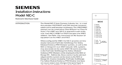
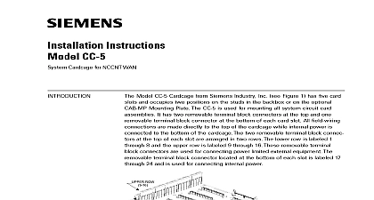
Installation Instructions NIC C Interface Card for NCCNT WAN Model NIC C from Siemens Industry Inc is a that provides network communication within and enclosures The network can be wired either 4 or Style 7 One NIC C is required in each Each NIC C occupies one HNET address NIC C supervises the network to insure proper Any faults that are detected by the NIC C reported to the NCCNT WAN for annunciation In the NIC C has diagnostic LEDs that indicate faults have been found Individual LEDs are for Loop A and Loop B faults as well as an for complete failure of the network The NIC C can be configured to perform ground fault detection on network on the system wiring method the NIC C short circuit faults to each individual segment the local network If a short occurs only the of wire between the two NIC Cs is affected a Style 4 system the network will be divided into sections Communication in each of the sections continue For a Style 7 network the fault will be and the network will continue to operate as a network See Figure 3a network port jack is included for connection of tools This jack is located on the front bezel are visible through the front bezel to indicate the configuration All switch selectable options are here This allows for easy confirmation of NIC C configuration settings without removing the from the CC 5 315 099320 5 supervision is accomplished through passive of the network signals No additional band is required Each NIC C continuously monitors network for activity and reports any problems to the WAN Restoration of faults is dynamic and does require a system reset 1 Network Interface Card Industry Industry Industry Inc Inc Inc Industry Inc Industry Inc TTTTTececececechnologies Di Di Di Division Di and Indicators front panel of the NIC C contains one reset switch fifteen LEDs one network and three HNET address switches as shown in Figure 1 reset switch is located on the top of the front panel Pushing the reset switch the NIC C operation LEDs follow the reset switch and their functions are defined as follows FAIL FAIL FAIL FAIL FAULT A FAIL B FAIL NETWORKS CAN Green NETWORKS HNET Green ON When illuminated that power for the NIC C is to the card OFF When illuminated that the card microprocessor failed OFF Not used in this applica OFF When illuminated that the HNET communication the NIC C has terminated and the goes into degrade mode applicable when card resides in the HNET OFF Not used in this applica OFF When illuminated that the NIC C has detected a negative or positive ground fault its network OFF When illuminated indi that the NIC C has detected a on Loop A open circuit or short OFF When illuminated indi that the NIC C has detected a on Loop B open circuit or short OFF Not used in this OFF When illuminated that the HNET network is NETWORKS XNET Green used in this application 7 illuminated indicates that the is configured as Style 7 see Pre S3 on page 4 Industry Inc Technologies Division 315 099320 5 4 illuminated indicates that the is configured as Style 4 see Pre S3 on page 4 illuminated indicates that ground detection is enabled see Pre S1 below illuminated indicates that ground detection is disabled see Pre S1 below rotary dial switches at the bottom of the front panel are used to set the HNET address of the NIC C following components must be set prior to inserting the card to the CC 5 refer Figure 2 Ground Fault Detection Control Press the lever down to enable ground detection Move the lever to the up position to disable ground fault detection to Figure 2 is only necessary to enable fault detection on one in the system If NIC Cs have ground detection enabled troubles will be to the NCCNT WAN a ground fault is NIC C Options 1 Network this switch to ON position for XNET is not in this 2 Network to ON for Style Set to OFF for 7 3 CAN Net enable CAN network not used in this 4 Future Use to OFF Industry Inc Technologies Division 2 Switch Location 315 099320 5 24 AWG min 12 AWG max 80 ohms max per pair CC 5s Use twisted pair or shielded pair Terminate the shield at one only one NCC 1F or Power Limited to NFPA 70 NEC 760 Maximum voltage 8V P P Maximum current 75mA Each pair independently Positive or negative ground detected at 80K ohms CC 5 pins 3 4 7 8 Reset Switch Momentarily Closed switch that when pressed will initiate a reset to the NIC C similar to a cold boot S6 S7 Network Address Switches Set the three digit HNET network address the NIC C using the three rotary dial address switches located near the bottom of front panel Refer to Figure 1 for the location of the switches The address for NIC C must be the same as the address selected for it in the NCCNTWAN To set address turn the pointers on each of the three dials to the numbers for the address For example if the address is 123 set the pointer for the HUN dial to set the pointer for the TENS dial to and set the pointer for the dial to The range of allowable addresses is from 001 to 251 leading zeros be used Do not use any address higher than 251 all system power before installation first battery then AC To power up the AC first then the battery Connect External Wiring the screw of the terminal by turning it counterclockwise the wire into the side of the terminal block the screw of the terminal block by turning it clockwise NIC C supports Style 4 and Style 7 wiring The screw terminals can accommodate one 12 24 AWG or two 16 24 AWG EOLR OHMS 1 2W 5 140 820350 END POINT SLOT OF CC 5 WITH NIC C INSTALLED 3 To NCC 1F Wiring Industry Inc Technologies Division 315 099320 5 24 AWG min 12 AWG max 80 ohms max per pair CC 5s Use twisted pair or shielded pair Terminate the shield at one only one NCC 1F or Power Limited to NFPA 70 NEC 760 Maximum voltage 8V P P Maximum current 75mA Each pair independently The NIC C provides an repeater for each pair Be sure to the pairs following proper polarity Do not the A and B pairs the NIC C from CC 5 will break the Removing power the NIC C does not the network Positive or negative ground detected at 80K on CC 5 pins 1 8 EOLR OHMS 1 2W 5 140 820350 END POINT B THIS PAIR FOR STYLE 4 ADDITIONAL OR NCC 1Fs A SLOT OF CC 5 WITH NIC C INSTALLED 3a Used As A Repeater NIC C plugs perpendicularly into one slot in the CC 5 card cage via two 96 pin connectors and can occupy any slot in the card cage Refer to Figure 4 the NIC C card into the card guides rightside up on the front panel is legible the card in until the card edge connectors contact receptacles on the motherboard that the DIN connectors of the card and the card aligned properly The card can only