Siemens NIC-C Network Interface Card, Installation Instructions

File Preview
Click below to download for free
Click below to download for free
File Data
| Name | siemens-nic-c-network-interface-card-installation-instructions-2318659470.pdf |
|---|---|
| Type | |
| Size | 1.05 MB |
| Downloads |
Text Preview
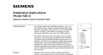
Installation Instructions NIC C Interface Card Model NIC C from Siemens Industry Inc is a card provides HNET XNET and CAN network communi within and between enclosures The HNET XNET can be wired either Class B Style 4 or Class X 7 For HNET one NIC C is required in each enclo Each NIC C HNET or XNET occupies one HNET See Table 1 for restrictions on the location of on the HNET and XNET configured for XNET the NIC C provides commu between FireFinder XLS Desigo Fire Safety PRO Modular systems as well as the or Desigo CC in an XNET network MXL systems also reside on the same XNET All events occurring the FireFinder XLS Desigo Fire Safety Modular PRO Modular will be displayed at the NCC or CC Additionally these events may be acknowl and the system can be reset via the NCC or CC Events initiated by FireFinder XLS Desigo Safety Modular Cerberus PRO Modular members cause output state changes inter panel logic in FireFinder XLS Desigo Fire Safety Modular PRO Modular panels Inter panel logic be FireFinder XLS Desigo Fire Safety Modular PRO Modular and MXL is not available One configured for XNET is required in each FireFinder Fire Safety Modular Cerberus PRO Modular connected to XNET This NIC C must reside in same enclosure as the PMI PMI 2 PMI 3 XLS Desigo Fire Safety Modular FCM2041 Cerberus PRO Modular the NCC GL is supported where display and of an individual XLS Desigo Fire Safety Modular PRO Modular system is required The NCC GL be connected to the XNET network The to HNET is not supported 1 Network Interface Card CAN network is also supported by NIC C It can be isolated within a given or extended external to the enclosure External CAN networks require an RNI OCM 16 or SIM 16 in the remote enclosure The CAN address of the does not need to be set single NIC C provides either HNET or XNET The CAN interface is available regard of the HNET XNET selection 315 033240 13 Inc Inc Inc Industry Inc Inc TTTTTececececechnologies Di Di Di Division Di NIC C supervises each network to insure proper operation Any faults that are by the NIC C are reported to the PMI PMI 2 PMI 3 XLS FCM2041 U2 Fire Safety Modular FCM2041 U3 Cerberus PRO Modular for annunciation addition the NIC C has diagnostic LEDs that indicate which faults have been Individual LEDs are included for HNET XNET Loop A and Loop B faults as well an LED for complete failure of the HNET or XNET network or the CAN network NIC C can also be configured to perform ground fault detection on both net NIC C isolates short circuit faults to each individual segment of the HNET XNET If a short occurs only the segment of wire between the two NIC Cs is In a Class B Style 4 system the network will be divided into two sections in each of the sections will continue For a Class X Style 7 network fault will be detected and the network will continue to operate as a single An HNET XNET network monitoring jack is included for connection of tools This jack is located on the front bezel NIC C supports the LCM 8 SCM 8 FCM 6 OCM 16 SIM 16 CAN modules LEDs visible through the front bezel to indicate the NIC C configuration All switch options are displayed here This allows for easy confirmation of the NIC C settings NIC C is compatible with the XNET Bridge Refer to the XNET Bridge installation P N 315 050017 for more details 4 ULC DCLB 7 ULC DCLC Canada ULC S524 requires that all interconnecting data communications links for be wired DCLC style 7 except for dedicated network communication to 1 Placement At The End Of a HNET Or XNET Network supervision is accomplished through passive monitoring of the network No additional bandwidth is required Each NIC C continuously monitors all for activity and reports any problems to the PMI PMI 2 PMI 3 XLS Desigo Fire Safety Modular FCM2041 U3 Cerberus PRO Modular In cases a reset at the PMI PMI 2 PMI 3 XLS FCM2041 U2 Desigo Fire Safety FCM2041 U3 Cerberus PRO Modular is required to clear network troubles Industry Inc Technologies Division 315 033240 13 and Indicators front panel of the NIC C contains one reset switch fifteen LEDs one network and three HNET address switches as shown in Figure 1 reset switch is located on the top of the front panel Pushing the reset switch re the NIC C operation LEDs follow the reset switch and their functions are defined as follows FAIL FAIL FAIL FAIL FAULT A FAIL B FAIL NETWORKS CAN NETWORKS HNET Green NETWORKS XNET 7 ON When illuminated indi that power for the NIC C is applied the card OFF When illuminated indicates the card microprocessor has failed OFF When illuminated indi that all CAN modules connected to NIC C are not communicating OFF When illuminated indi that the HNET communication the NIC C has terminated and the goes into degrade mode OFF When illuminated indi that the XNET communication with NIC C has terminated OFF When illuminated indi that the NIC C has detected either negative or positive ground fault on its OFF When illuminated indi that the NIC C has detected a on Loop A open circuit or short OFF When illuminated indi that the NIC C has detected a on Loop B open circuit or short OFF When illuminated indi that the CAN network is enabled illuminated indicates that the network is enabled illuminated indicates that the network is enabled illuminated indicates that the is configured as Class X Style see Pre Installation S3 on page 4 Industry Inc Technologies Division 315 033240 13 following components must be set prior to inserting the card into the CC 5 refer Figure 2 4 illuminated indicates that the is configured as Class B Style see Pre Installation S3 on page 4 illuminated indicates that ground detection is enabled see Pre on page 4 illuminated indicates that ground detection is disabled see Pre on page 4 rotary dial switches at the bottom of the front panel are used to set the HNET address of the NIC C Ground Fault Detection Control Press the lever down to enable ground fault Move the lever to the up position to disable ground fault detection Refer Figure 2 is recommended to enable ground fault detection on ONLY one NIC C in the system for HNET and if used one for XNET If multiple NIC Cs have ground fault detection multiple troubles will be reported to the PMI PMI 2 PMI 3 XLS FCM2041 U2 Fire Safety Modular FCM2041 U3 Cerberus PRO Modular when a ground is present In all cases at least one NIC C must have ground fault detection PIN DIN CONNECTOR NIC C Options 1 Network Selection this switch to the ON for HNET Set to the OFF for XNET 2 Network Style to ON for Class B Style 4 to OFF for Class X Style 7 3 CAN Network enable to ON if CAN network is Set to OFF if CAN network not used 4 Future Use to OFF Reset Switch Momentarily Closed that when pressed will initiate a hard to the NIC C similar to a cold boot S6 S7 Jumper Settings Class B Style 4 wiring is used for an application remove P2 except on the NIC C that is to the NCC 2F card When Class 7 wiring is used for an