Siemens PAB-ENCL PAB-ENCL-R and PAB2-ENCL PAB2-ENCL-R, Installation Instructions

File Preview
Click below to download for free
Click below to download for free
File Data
| Name | siemens-pab-encl-pab-encl-r-and-pab2-encl-pab2-encl-r-installation-instructions-3710469528.pdf |
|---|---|
| Type | |
| Size | 723.54 KB |
| Downloads |
Text Preview
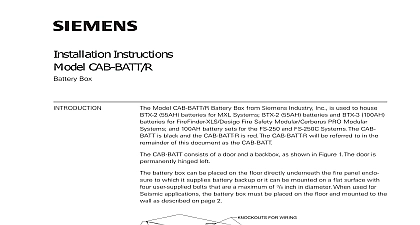
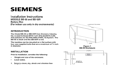
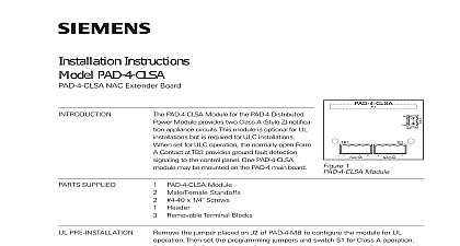
INSTRUCTIONS PAB ENCL R and PAB2 ENCL R HU and 2 HU Black Red Enclosures for use with PADs and Booster Amplifiers model PAB ENCL P N S54339 A8 A1 is black in color and is used to accommodate the following PAD 5 Intelligent Notification and Auxiliary Power Expander P N S54339 A5 A1 See Instructions ID A6V101030358 PAD 4 Adapter P N S54339 A13 A1 See Instructions Document ID A6V101061184 PAD 3 Adapter P N S54339 A12 A1 See Instructions Document ID A6V101061175 Adapter kit Model BAAP Booster Amp Adapter Plate P N S54339 A14 A1 See Instructions ID A6V101061186 model PAB ENCL R P N S54339 A9 A1 is red in color and is used also to accommodate the same modules model PAB 2 ENCL P N S54330 A9 A1 is black in color and is used to accommodate a maximum of of the above modules in the same enclosure The same applies to the red model PAB 2 ENCL R P N enclosures must be mounted on a flat surface with four user supplied bolts that are a maximum of 5 16 diameter and a minimum of in diameter The PAB 2 ENCL requires six bolts for seismic applications enclosures contain enough space to mount a set of BP 61 two 18AH batteries in the bottom for the and a set of BTX 1 two 35AH batteries for the PAB2 ENCL seismic applications use the battery bracket Model FHA2032 U1 P N S54430 B43 A1 This is good only for the BP 61 two 18AH batteries Both enclosures can accommodate this to installation consider the following Mounting height for access to the Enclosure Weight and size of the Enclosure Local codes the Enclosure Refer to Figures 2 and 3 Select a clean dry shock and vibration free flat surface Position the enclosure clear of obstructions so that the front door opens freely Mark the locations of the two upper mounting bolts of the enclosure on the wall Drill the two holes marked and attach the two top bolts leaving a small gap between the wall and bolt Place the enclosure over the two top bolts and allow it to slide down over the bolts Mark drill and install the two bottom bolts in the enclosure all four bolts securely against the back wall of the enclosure Siemens Industry Inc Building Technologies Division ROUTING compliance with NEC Article 760 all power limited fire protective signaling conductors must be separated minimum of from all of the following wiring located within the enclosure Electric light Power Class 1 or non power limited fire protective signaling conductors meet the above requirements the following guidelines must be observed when installing modules and wire routing installing power limited field wiring the installer must comply with NEC Article 760 which states fire alarm power limited circuits are install using types FPL FPLR FPLP or permitted substitute provided these power limited cable conductors extending beyond the jacket are separated by minimum of 6.35mm or by a nonconductive sleeve or nonconductive barrier from all other If an energy limited cable or equivalent is not used within the enclosures then the following do not apply In that case be sure to follow standard wiring practices high voltage and non power limited wiring must be kept separate from power limited wiring A must be maintained with high voltage and non power limited wiring running in separate conduit from power wiring To avoid induced noise transfer of electrical energy from one wire to another input wiring isolated from high current output and power limited wiring Improper wiring installation may improper operation Avoid pulling one multi conductor cable for the entire system Instead separate current input output from low current Wiring within the cabinet should be routed around the perimeter of cabinet It should not cross the printed circuit board where it could induce noise into the sensitive or pick up unwanted RF noise from the switching power supply circuit 1 PAD 5 Wire Routing Locations Non Power Limited High Voltage AC power Power Limited Power Limited Power Limited Power Limited FOR 2 PAB ENCL R Mounting Holes and Knockouts FOR FOR 3 PAB2 ENCL R Mounting Holes and Knockouts PAB2 ENCL Color RAL9011 Black PAB2 ENCL R Color RAL3020 Red 21 lbs for PAB ENCL R 36 lbs for PAB2 ENCL R Enclosure PAB only 16 X 3.5 X 24 outside dimensions Enclosure PAB2 only 16 X 5.5 X 40 outside dimensions All six knockouts for PAB ENCL R are NPT sizes All eight knockouts on the right side for PAB2 ENCL R are combination NPT sizes The knockouts on the left side are NPT sizes for both Enclosures 16 Ga 060 Cold Rolled Steel security disclaimer products and solutions provide security functions to ensure the secure operation of building comfort safety security management and physical security systems The security functions on these products and are important components of a comprehensive security concept is however necessary to implement and maintain a comprehensive state of the art security concept that customized to individual security needs Such a security concept may result in additional site specific action to ensure that the building comfort fire safety security management or physical security for your site are operated in a secure manner These measures may include but are not limited to networks physically protecting system components user awareness programs defense in depth additional information on building technology security and our offerings contact your Siemens sales or department We strongly recommend customers to follow our security advisories which provide on the latest security threats patches and other mitigation measures http www siemens com cert en cert security advisories htm PAGE HAS BEEN LEFT INTENTIONALLY BLANK PAGE HAS BEEN LEFT INTENTIONALLY BLANK ID A6V101061125 enUS b A5Q00072470