Siemens PAD-4 Encl Enclosure and Door for PAD-4 Distributed Power Module NAC Expander, Installation and Power Limited Wiring Instructions
File Preview
Click below to download for free
Click below to download for free
File Data
| Name | siemens-pad-4-encl-enclosure-and-door-for-pad-4-distributed-power-module-nac-expander-installation-and-power-limited-wiring-instructions-2748561903.pdf |
|---|---|
| Type | |
| Size | 658.60 KB |
| Downloads |
Text Preview
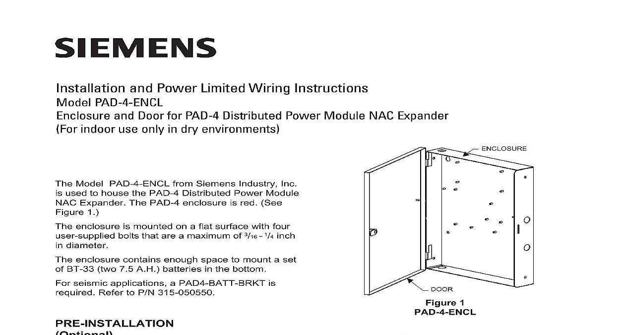
Installation and Power Limited Wiring Instructions PAD 4 ENCL and Door for PAD 4 Distributed Power Module NAC Expander indoor use only in dry environments Model PAD 4 ENCL from Siemens Industry Inc used to house the PAD 4 Distributed Power Module Expander The PAD 4 enclosure is red See 1 enclosure is mounted on a flat surface with four bolts that are a maximum of 3 16 1 4 inch diameter enclosure contains enough space to mount a set BT 33 two 7.5 A H batteries in the bottom seismic applications a PAD4 BATT BRKT is Refer to P N 315 050550 desired remove the door before mounting the by first removing the ground strap and then the door up and off its hinges Refer to Figure 2 to installation consider the following Mounting height for access to the enclosure Weight and size of the enclosure codes the enclosure Select a clean dry shock and vibration free Position the enclosure clear of obstructions so that front door opens freely and the controls and are easily accessible Industry Inc Technologies Division Park NJ 315 050081 2 1 PIN the Door from the PAD 4 ENCL 2 Canada Limited Technologies Division Kenview Boulevard Ontario L6T 5E4 Canada Mark the locations of the two upper mounting bolts the enclosure on the wall Refer to Figure 3 Drill the two holes located in the previous step screw in the top bolts leaving a small gap the wall and each top bolt Place the enclosure over the two top bolts and it to slide down over the bolts Refer to 4 Mark drill and install the two bottom bolts in the Tighten all four bolts securely against the back of the enclosure compliance with UL 864 all power limited fire signaling conductors must be separated a of inch from all of the following wiring within a control panel light 1 or non power limited fire protective conductors meet these requirements the following guidelines be observed when installing modules and to this control panel installing power limited field wiring the installer comply with CEC and NEC article 760 which fire alarm power limited circuits are installed using FPL FPLR FPLP or permitted substitute cable these power limited cable conductors extend beyond the jacket are separated by a minimum of in 6.35 mm or by a nonconductive sleeve or barrier from all other conductors If power limited wiring is not used within the enclosure then the following guide do not apply In that case be sure to standard wiring practices avoid induced noise transfer of electrical energy one wire to another keep input wiring isolated high current output and power limited wiring wiring installation may cause improper Avoid pulling one multi conductor cable for entire system Instead separate high current from low current within the cabinet should be routed around the of the cabinet It should not cross the circuit board where it could induce noise into sensitive microelectroincs or pick up unwanted RF from the switching power supply circuit PAD 4 ENCL 3 Mounting Holes BOLTS PLACES SUPPLIED 4 the PAD 4 ENCL Entering Enclosure Limited Wiring entering the enclosure from the top bottom left side of the backbox is considered non power wiring Wiring must be in the shortest route must not overlap any other wiring Refer to 5 Limited Wiring entering the enclosure from the top right or side of the backbox is considered power limited must be in the shortest route and must not any other wiring Refer to Figure 5 Wiring System is designed to operate from an external VAC 50 Hz 60 Hz power source The source must have a separate or dedicated breaker Wire in accordance with local codes NEC 760 and CEC Remove the knockouts in the enclosure for the of field wiring Refer to Figure 6 for the of knockouts 6 Knockouts Pull all field wiring into the enclosure Do not dress wiring until the location of all the equipment is the wiring from the external power source the approximate location of the power supply the backbox is installed and the wiring com finish the installation by replacing the door and ground strap if removed the outer door by placing it on its hinges the ground strap on both the door and See Figure 7 For Canadian Installations place on front door label P N A5Q00053840 supplied with See Figure 8 Non power Limited High Voltage AC power or B Non power Limited High Voltage AC power or A Non power Limited Battery wiring if separate enclosure Non power Limited Battery wiring if separate enclosure or D or C Power Limited or F or G Limited or E or G Power Limited or E or F 5 Routing in the PAD 4 ENCL STRAP 14AWG LABEL POWER OPENING LE COURANT D 8 View of the PAD 4 ENCL the Ground Strap on the PAD 4 ENCL 7 enclosure x 3.00 D x 18.00 H Approx 10 lbs Industry Inc Technologies Division Park NJ 315 050081 2 ID A6V10372632 Canada Limited Technologies Division Kenview Boulevard Ontario L6T 5E4 Canada