Siemens RCC-2 RCC-2R and RSE-1 Remote Control Centers, Installation Instructions

File Preview
Click below to download for free
Click below to download for free
File Data
| Name | siemens-rcc-2-rcc-2r-and-rse-1-remote-control-centers-installation-instructions-5987360142.pdf |
|---|---|
| Type | |
| Size | 819.36 KB |
| Downloads |
Text Preview
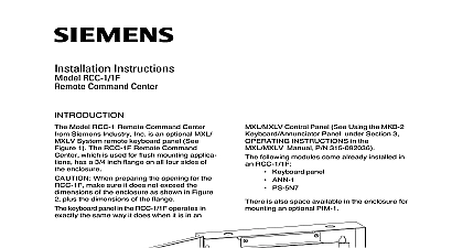
INTRODUCTION Instructions RCC 2 R and RSE 1 Control Centers Model RCC 2 R Remote Command Center Siemens Industry Inc See Figure 1 the option to remotely annunciate and MXL and MXL IQ system status The and RSE 1 provide for mounting and of the PIM 1 printer interface module following modules come already installed in RCC 2 R Keypad LCD Display ANN 1 Driver Board PS 5N7 Power Supply following modules come already installed in RSE 1 ANN 1 Driver Board PS 5N7 Power Supply RCC 2 R has a mounting location for an PIM 1 The RSE 1 has the same and requires the PIM 1 RCC 2 R comes with a clear lens on a door This limits access to the control of system or the display The door is secured a T 45 lock set keypad on the RCC 2 R operates the same the MKB in the MXL enclosure See Section 3 the MXL Installation Operation and Mainte Manual P N 315 092036 for the com operating instructions for the control panel remove all power before installa first the battery and then the AC the Network Address installing the RCC RSE set the network on S1 SW1 and S1 SW2 of the ANN 1 Refer to Table 1 for switch settings See Setting the Network Address in Section 2 of the MXL MXLV Manual P N 1 SETTINGS ON THE ANN 1 SETTINGS FOR 1 Remote Command Center Switches S1 SW3 and S1 SW4 are for use Switch S1 SW5 is used to supervision Industry Inc Technologies Division Park NJ 315 099160 8 Building Technologies Ltd Safety Security Products Kenview Boulevard Ontario 5E4 Canada Supervision switch S1 SW5 on the ANN 1 to select or supervision If your ANN 1 has a switch position 1 indicated on the left hand side the printing on the switch SW1 on S1 is at extreme right hand side of S1 regardless of other marking set for supervision Closed ON set for non supervision Open OFF When you select non supervision for annunciator there must also be and only one supervised annun at the same address mounting the RCC RSE follow these Remove the cover assembly from the Disconnect at P1 the cable from the PS 5N7 Remove the PS 5N7 from the backbox See 2 and 3 Set the panel to one side the following when mounting the cid 127 Mounting height for visual and manual to the keypad cid 127 Weight and size of the enclosure cid 127 mounting codes mount the RCC RSE follow these steps Fasten the RCC RSE backbox securely to a dry shock free and vibration free using the four mounting holes Refer to Figure 4 for the of the backbox and the location the mounting holes Position the RCC backbox clear of obstructions so that door opens freely and the indicators and are easily accessible Pull all field wiring into the backbox and the wiring to the approximate location which it will go Install field wiring to the Refer to PS 5N7 Installation P N 315 092729 a PIM 1 is required mount it to the set of standoffs to the right of the PS 5N7 Figures 2 and 3 P1 on the PIM 1 to P1 on the ANN 1 the 14 inch cable P N 555 192242 P2 on the PIM 1 to P1 on the PS 5N7 the 14 inch cable P N 555 192242 to PS 5N7 Installation Instructions 315 092729 PIM 1 Installation P N 315 091462 and Figure 6 a PIM 1 is not installed reconnect P1 on ANN 1 to P1 on the PS 5N7 Reattach the cover assembly to the Refer to the MXL MXLV Manual P N 315 for additional information on the of the keypad RATINGS to the following Installation Instructions as 315 095097 315 048860 315 090911 315 085062 315 093495 315 099082 315 095931 Manual P N 315 092036 DISPLAY DOOR 2 Exploded View OUTER DOOR 3 Exploded View The RCC RSE MUST have an earth ground connected to the chassis Wire shield or conduit is an acceptable ground Use any available unused unpainted stud for chassis grounding 4 RSE 1 Dimensions NOT USE NOT USE 120 OHMS 5 140 820150 IN AN SMB 2 120 OHMS 5 140 820150 Use a minimum wire gauge of 18 AWG Use a maximum of 80 ohms per pair of for the network connections Use shielded twisted pair for network Terminate the shield ONLY at the MMB SMB PSR 1 only allowed in systems with MMB 2 DO NOT place the PS 5N7 at the end of network Style 7 only This configuration is power limited to NFPA according to NEC 760 All wiring supervised Refer to Wiring Specification for MXL MXL IQ MXLV Systems P N 315 092772 revision or higher for additional wiring information MNET Maximum voltage 8V peak to peak current 150mA Power Supply and Network Wiring Diagram in RCC RSE Enclosure Style 4 5 FOR 2 3 4 600 290505 MOM 4 SMB 2 10 11 12 13 14 P N 555 190967 OHM 5 140 820150 THIS CONNECTION TO ANY THE FOLLOWING TERMINATIONS with PS 35 BN4 002 UL 9 12 9 12 3 6 1 2 18 19 LIMITED VDC VDC RETURN A PRIMARY LIMITED B SECONDARY LIMITED IN AN RSE 1 Use a minimum wire gauge of 18 AWG Use a maximum of 80 ohms per pair of for the network connections Use shielded twisted pair for network Terminate the shield ONLY at the MMB SMB PSR 1 only allowed in systems with MMB 2 DO NOT place the PS 5N7 at the end of network Style 7 only This configuration is power limited to NFPA according to NEC 760 Refer to Wiring Specification for MXL MXL IQ MXLV Systems P N 315 092772 revision 6 higher for additional wiring information MNET Maximum voltage 8V peak to peak current 150mA Power Supply and Network Wiring Diagram in RCC RSE Enclosure Style 7 6 page is intentionally blank page is intentionally blank page is intentionally blank Industry Inc Technologies Division Park NJ 315 099160 8 Building Technologies Ltd Safety Security Products Kenview Boulevard Ontario 5E4 Canada