Siemens SA-3I SA-11 P Air Duct Detectors, Installation Instructions
File Preview
Click below to download for free
Click below to download for free
File Data
| Name | siemens-sa-3i-sa-11-p-air-duct-detectors-installation-instructions-9256740138.pdf |
|---|---|
| Type | |
| Size | 885.12 KB |
| Downloads |
Text Preview
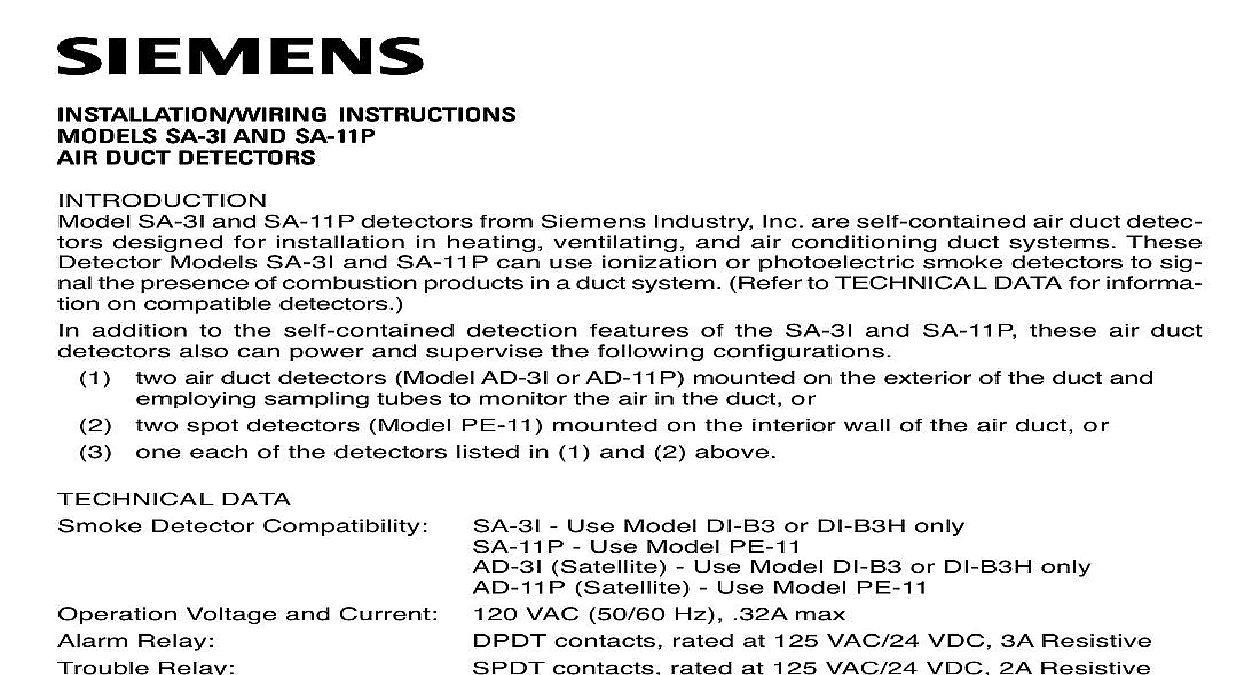
TION WIRING INSTRTRTRTRTRUCTIONS INS INS INS INS SS SS SS SS SAAAAA 3I SAAAAA 1 1 1 1 11P1P1P1P1P S S AND S S DUCT DETECT DUCT DETECT DUCT DETECTORORORORORSSSSS DUCT DETECT DUCT DETECT SA 3I and SA 11P detectors from Siemens Industry Inc are self contained air duct detec designed for installation in heating ventilating and air conditioning duct systems These Models SA 3I and SA 11P can use ionization or photoelectric smoke detectors to sig the presence of combustion products in a duct system Refer to TECHNICAL DATA for informa on compatible detectors addition to the self contained detection features of the SA 3I and SA 11P these air duct also can power and supervise the following configurations air duct detectors Model AD 3I or AD 11P mounted on the exterior of the duct and sampling tubes to monitor the air in the duct or spot detectors Model PE 11 mounted on the interior wall of the air duct or one each of the detectors listed in 1 and 2 above DATA Detector Compatibility Voltage and Current Relay Relay Detector Sensitivity Indicator Range Range Humidity Range Duct Velocity Range Tube Pressure Range Industry Inc Technologies Division Park NJ 315 096274 4 Use Model DI B3 or DI B3H only Use Model PE 11 Satellite Use Model DI B3 or DI B3H only Satellite Use Model PE 11 VAC 50 60 Hz 32A max contacts rated at 125 VAC 24 VDC 3A Resistive contacts rated at 125 VAC 24 VDC 2A Resistive set for air duct application detector label on smoke detector displays steady or flashing red through air duct cover 0OC to 100O F 37.8OC per UL 268 268A using DI B3 Altitude range is 0 to 4000 feet using DI B3H Altitude range is 3000 to 8000 feet sea level sea level using PE 11 No altitude limitations detectors by altitude to 93 non condensating RH per UL 268 268A to 4000 ft min 300 to 4000 ft min to 1.07 inches of water 0.006 to 1.07 inches of water Building Technologies Ltd Safety Security Products Kenview Boulevard Ontario 5E4 Canada air duct detectors are designed for detection of products of combus in a duct system They are not to be used for open area protection the SA 3I or SA 11P is in operation a sample of air is drawn from the duct and passed the sampling chamber at low velocity by means of the inlet sampling tube The air passes through the smoke detector mounted in the duct housing and is exhausted back into the via the outlet sampling tube Indication normal operation the green Power LED on the power supply control board located in the wiring of the SA 3I 11P is lit indicating that AC power is being applied The alarm and trouble are in non alarm and non trouble states during standby operation Indication smoke detector used with the SA 3I 11P includes an LED for visual alarm indication If the air detector is not visible a remote alarm lamp can be used for visual alarm indication See 6 for models Operation alarm signal from the smoke detector within the SA 3I 11P or from a satellite detector causes alarm relay in the SA 3I 11P to energize Model SA 3I 11P can be wired for direct alarm relay control of normally energized and de energized Refer to ELECTRICAL WIRING for details When all products of combustion are cleared from duct system the Model SA 3I 11P can be reset by operating the RESET switch with the Reset key Air duct detectors SA 3I 11P cannot be used for releasing service Condition trouble condition in the SA 3I 11P or in a satellite unit due to a loss of detector supervision causes trouble relay in the SA 3I 11P to de energize Loss of AC power to the SA 3I 11P results in the Power LED turning off and the trouble relay de energizing THE AIR DUCT HOUSING on Duct System air duct detector should be located in the main supply duct downstream from the filters and so as to operate reliably in case of smoke in any part of the air stream In instances where filters are capable of removing smoke a detector should be installed both upstream and down from the filters air duct detectors because they use sampling tubes which monitor the full width of an air duct the limitations of spot type smoke and heat detectors in the duct However since stratifica can occur in the air stream after a long duct run it is desirable to locate the detector after bends or which create turbulence and hence a more homogeneous mixture of air The detector should possible be located a minimum of six duct widths downstream from the source of turbulence Figure 1 A 12 inch by 12 inch access hole should be cut in the duct adjacent to the detector permit checking and cleaning the sampling tubes air duct detector should be located in the air handling as shown in Figure 2 and should be in conformance NFPA Pamphlet No 90A Air Conditioning and Venti Systems and with NFPA 72 National Fire Alarm Code publications are available from the National Fire Pro Association Batterymarch Park Quincy Massachu The detector on the return air side of the blower should located at a point prior to exhausting air from the building diluting return air with outside air The detector on the sup air side of the blower should be downstream of the blower detectors should be wired into the system so that they shut down the blowers and operate dampers required the Air Duct Housing See Figure 3 Affix the adhesive backed gaskets Item 1 to the back of the detector housing 2 so that the larger on the gasket lines up with the sampling tube hole on the sampling chamber and the hole with the housing mounting hole Mounting of Duct TUBE TUBE LEAST DUCT 1 Locations in Duct Systems 2 Sampling Tube Gasket Screw No 10 1 Plug Housing Lockwasher Detector PE 11 Inlet Sampling Tube Rubber Stopper DB ADPT Base Adapter Ionization Detector Cover Sensitivity Test Jack Lid Outlet Sampling Tube Template Screw No 10 11 2 Detector DI B3 DI B3H Cover Gasket PE 11 Detector Cover Screw No 6 Bracket Screw 3 16 Screw 8 32 P 3 View Affix the adhesive backed template 5 to the side of the ductwork Drill the four 0.110 diameter holes with a No 35 drill bit and cut or punch out two 7 8 inch holes as indicated on the template Attach the appropriate model housing to the air duct using two No 10 1 inch screws 6 and also two No 10 1 inch screws 7 with lockwashers 8 Cut a 12 inch by 12 inch access hole in the duct adjacent to the housing to permit checking and of the sampling tubes The access hole must be covered and sealed when not in use Tube Selection insure accurate air sampling inlet sampling tubes are available in four lengths To select the length determine the outside width of the duct Select the sampling tube nearest to but than the duct width Table 1 The outlet sampling tube for all ducts is a fixed length of 4 10.1 cm Trim the inlet sampling tube at the job site as described below 1 Sampling Tube Selection Chart Sampling Tube Model No Standard Tube Length Duct Width ft 9 in or less ft 9 in 3 ft 3 in ft 3 in 6 ft 3 in or less ft 3 in 9 ft 9 in or less than 9 ft 9 in factory 2 ft 3 ft 6 in 6 ft 6 in ft Each model is manufactured with a different number and size of hole Therefore only the tube must be used for the specified duct width 4 Tube Orientation the Inlet Sampling Tube See Figure 4 Measure the outside width of the duct Add 2.25 inches to obtain proper length of tube Example width of duct 2.25 inches 2.25 in of sampling tube ft 8.25 in ft 6in length 2 ft 8.25 in determines Table 1 above the model of the appropriate sampling tube STA 3