Siemens SNC Serial Network Card for USB Application with Windows, Installation Instructions
File Preview
Click below to download for free
Click below to download for free
File Data
| Name | siemens-snc-serial-network-card-for-usb-application-with-windows-installation-instructions-6209734185.pdf |
|---|---|
| Type | |
| Size | 922.48 KB |
| Downloads |
Text Preview
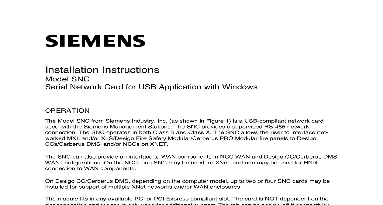
Instructions SNC Network Card for USB Application with Windows Model SNC from Siemens Industry Inc as shown in Figure 1 is a USB compliant network card with the Siemens Management Stations The SNC provides a supervised RS 485 network The SNC operates in both Class B and Class X The SNC allows the user to interface net MXL and or XLS Desigo Fire Safety Modular Cerberus PRO Modular fire panels to Desigo DMS and or NCCs on XNET SNC can also provide an interface to WAN components in NCC WAN and Desigo CC Cerberus DMS configurations On the NCC one SNC may be used for XNet and one may be used for HNet to WAN components Desigo CC Cerberus DMS depending on the computer model up to two or four SNC cards may be for support of multiple XNet networks and or WAN enclosures module fits in any available PCI or PCI Express compliant slot The card is NOT dependent on the connection and the tab is only used for additional support The tab can be scored off if connectivity are encountered Depending on the model either one or two SNC modules comes pre installed Management Station computers Hardware installation instructions for the SNC when it is not factory can be found in the Physical Installation section of this document and Indicators LEDs are located above X1 and are in top to bottom order See Figure 1 for more details Description OK OK A B to indicate network is data to indicate data to to indicate individual A select to indicate individual B select If LED is steady indicates a Class X fault on that channel Industry Inc Infrastructure 1 Module Board SNC is assigned to a standard COM port by Windows when the drivers are installed The drivers come pre installed in NCC Desigo CC Cerberus DMS The SNC driver installations are covered in Driver Installation section of this document COM port assigned to the SNC can be viewed in the Windows Device Manager One SNC card one COM port On Windows XP systems the used COM port will be the first or lower port assigned for the SNC card On Windows 7 or Windows 10 systems the used COM port is USB serial port assigned with the FTDI driver available Device Manager is accessible in Windows as follows 7 or 10 the Start menu and then click Control Panel this will open a new window on the Desktop the Control Panel options Address bar of the Control Panel window should end with the Control Panel location followed by a the right arrow to display the available additional locations and then select and click All Control Item On the updated screen select and click Device Manager Industry Inc Infrastructure OKHOST OKCH ACH BSIDE VIEWRESETfirealarmresources com 2 shows a sample Windows 7 or 10 Device Manager view and a typical assignment of COM ports a PC with two SNC boards installed COM13 and COM14 The port assignments for the SNC are USB Serial Port once installed and under Properties the FTDI driver is identified 2 Manager View port assignment can be changed to agree with any port assignment at the time of install or update board can handle XNET and either board can handle HNET There is no difference in the boards XNET and HNET are different protocols so HNET wiring should go to the board with the COM assigned to HNET and likewise XNET wiring should go to the board with the COM port assigned to the Desigo CC Cerberus DMS the wiring to the cards should match the card ID assignments in the Driver configuration Industry Inc Infrastructure INSTALLATION 1 Remove all Windows PC power before installation 2 The SNC connects to the motherboard internal USB2.0 connector via a cable harness provided Step 7 below On most motherboards the USB2.0 header pin out consists of nine pins arranged in rows which allows for two USB connections Normally but NOT always the pins for USB1 and USB2 in separate rows as shown below 5 S GND is also colored black and it is NOT required When the cable assembly provided is to the 4 pins row simply leave the S GND position unplugged On some motherboards 10 2 x 5 or 8 pins 2 x 4 headers may be present Connect as shown above USB2.0 connectivity verified for Comark 2nd and 4th generation motherboards The SNC only interfaces with motherboards that use the internal USB2.0 connector as shown Other motherboard connections are NOT compatible Verify its pin assignments before use install the SNC in a computer in which it is not factory installed follow the steps listed below Unscrew the two knurled knobs on the rear of the computer computer enclosure may have physical characteristics Slide the cover back an inch or so and lift it off The SNC installs into any free PCI or PCI Express compliant slot in the computer Select a slot remove the blank cover keeping the screw The card is NOT dependent on the slot connection and the tab is only used for additional The tab can be scored off if connectivity problems are encountered Remove the terminal block from the SNC by removing the two screws that hold it to the bracket Place the SNC into the open slot so that the SNC card edge extends through the opening in the of the PC Align the SNC with the card edge connector in the computer and press it firmly into place Connect the SNC via X3 connector to the mother board internal USB connection with the cable P N A5Q00070675 provided Secure the SNC by installing the screw that held the blank cover Refer to Step 3 Replace the computer cover and tighten the knurled knobs or equivalent Reattach the terminal block by sliding it onto the SNC card edge and install the two screws This a keyed connection and will only install one way After the SNC is installed install the SNC drivers following the instructions in the Driver section of this document Industry Inc Infrastructure PIN ASSIGNMENTSfirealarmresources com CONNECTIONS HNET XNET connections are made on terminals 1 4 of the terminal block on the front of the SNC Step 4 in Physical Installation The primary pair or network A is on terminals 1 and 2 The pair or network B is on terminals 3 and 4 Install a 120 ohm EOLR P N 140 820350 on 1 and 2 as well as terminals 3 and 4 Class B networks connect only the primary pairs Network A Class X networks connect to both the primary Network A and secondary Network B pairs XNET See Figure 3 for wiring details Network HNET Figure 4 for wiring details Industry Inc Infrastructure 3 XNET Connections to the Wiring Specification for MXL MXL IQ and MXLV Systems P N 315 092772 revision 6 or higher for wiring information No EOLR required for NIC C The screw terminals can accommodate one 12 24AWG or two 16 24AWG From the SNC to NIM 1R NIM 1W or SNC Ohms max per pair twisted pair 5 line to line twisted pair 3 line to line 4 line to shield From the SNC to NIC C feet 33.8 ohms max per pair between CC 5s CC 2s twisted pair 25 max line to line twisted pair 15 max line to line 2 max line to shield Use twisted pair or twisted shielded pair Terminate shields at one end only Power limited to NFPA 70 per NEC 760 CC 5 terminals 9 14 are not connected and can be used to tie shields together Positive or negative ground fault detected at 10K ohms on pins 3 4 7 8 of the NIC C Each pair independently supervised Maximum voltage 8V P P Maximum current 75mA during message transmission Industry Inc Infrastructure NOTE 8 MUST BE IN SAME ENCLOSURE AS THE PMI DO NOT USEDO NOT USEDO NOT USEDO NOT USEONE SLOT OF CC 5NIC C12345PAIR ASUPERVISEDPOWER LIMITEDPAIR B OMIT FOR CLASS B SUPERVISEDPOWER LIMITEDMOM 4TB3 OR TB4NIM 1R NIM 1W1234TO ADDITIONALNIM 1Rs NIM 1Ws SNCs OR NIC CsSNCLOCATED INSIDE NCC DESIGO CC CERBERUS DMSNOTE IF THE NCC DESIGO CC CERBERUS DMS IS LOCATED AT THE END OFTHE XNET NETWORK INSTALLEOLR P N 140 8203