Siemens SNU ASSY Single Node Upload, Installation Instructions

File Preview
Click below to download for free
Click below to download for free
File Data
| Name | siemens-snu-assy-single-node-upload-installation-instructions-1739028546.pdf |
|---|---|
| Type | |
| Size | 1.62 MB |
| Downloads |
Text Preview
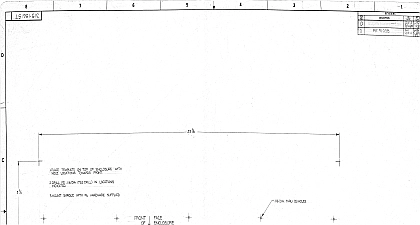
ASSY Node Upload Instructions Industry Inc Building Technologies Division Notice information is subject to change without notice by Siemens Inc Companies names and various data used in examples are unless otherwise noted No part of this document may be or transmitted in any form or by any means electronic or for any purpose without the express written permission of Industry Inc software described in this document is furnished under a license and may be used or copied only in accordance with license further information contact your nearest Siemens Industry Inc 2017 Copyright Siemens Industry Inc the Reader feedback is important to us If you have comments about this manual submit them to SBT technical editor us sbt siemens com Desigo CC Cerberus DMS APOGEE XLS FireFinder and Sinteso registered trademarks of Siemens Industry Inc product or company names mentioned herein may be the trademarks their respective owners 2017 03 30 ID A6V10525432 enUS c of contents This Document 4 Assy Remote Zeus Access to PMIs Single Point Upload 5 Sales Kit S54430 C19 A1 7 Electrical Ratings 8 the SNU Sales Kit 8 Wiring inside the enclosure 9 Configuring the SNU Assy 13 and Using the Virtual Serial Port Software on the Zeus PC 17 Closing VirtualHere client when all operations are complete 25 This Document guide describes the installation of the SNU Assy for remote between Zeus and XLS control panels PMI Audience Engineers provide the basic installation of devices and systems for a customer at the customer site They have the training appropriate to function and to the products devices and systems to be installed They also familiar with the applied operating system s and the related environment Field engineers are responsible for infrastructure for example hardware communication network and so Disclaimer have checked the contents of this manual for agreement with the and software described Since deviations cannot be precluded we cannot guarantee full agreement However the data in this are reviewed regularly and any necessary corrections included in editions Suggestions for improvement are welcome SNU Assy Remote Zeus Access to PMIs Point Upload SNU Assy provides a solution for remote uploading from a single point a PC running the Zeus configuration tool to remotely located XLS PMIs is accomplished using a dedicated Ethernet network separate from all system networks XNET HNET DNET and any network that may present during installation It employs device servers that have three connections power Ethernet and USB Note that the between the Zeus PC and SNU Assy employs SSL for data Up to 64 PMIs can be attached to the dedicated Ethernet for access the Zeus PC physical connection between the PMI 1 and the SNU Assy requires a cable P N S54430 A4 A1 physical connection between the PMI 2 and the SNU Assy is the USB port currently used for Zeus communication 1 Assy Architecture SNU Assy allows a Zeus user to perform operations remotely via the Ethernet network This network can be used to perform the operations Transfer of configuration to a PMI Extraction of configuration from a PMI Transfer of audio files into the system Extraction of watchdog log Extraction of history logs Extraction of walktest logs Transfer of HNET module app firmware for updates Transfer of CAN firmware for updates Transfer of DAC firmware for updates Ethernet network is not part of the building LAN and no fire network is provided hardware is mounted in a separate enclosure from the PMIs The shown on the left of the following figure contains the SNU Assy and the enclosure on the right represents the existing XLS PMI Figure 2 represents a typical configuration at an XLS PMI Single Node Upload solution requires kit assembly and should be within 5 feet of the PMI it is connected to See Figures 4 and 5 for requirements Node kit Fire 2 Location Configuration SNU Sales Kit S54430 C19 A1 kit contains the following parts ENCL 01 enclosure with keyed door P N S54465 C63 A1 PS 5A power supply mounting screws included P N 500 492369 SNU ASSY SINGLE NODE UPLOAD P N S54430 A3 A1 assemble the kit the following items are required but not included in the 1 14 18 AWG cable for PS 5A power supply 1 Ethernet cable Ethernet switches dedicated and properly engineered Ethernet infrastructure to connect all the SNU Assy units and provide connections as desired for the Zeus PC This equipment must be in a locked enclosure 3 View of SNU without cables SNU Electrical Ratings A A Parameter screw terminal current standby current alarm current backplane current backplane current SNU Assy may be powered using any power supply listed for Fire with outputs including Siemens PAD 3 PAD 4 PSC 12 and PSX 12 a PSC 12 or PSX 12 is used to supply 24 VDC to the SNU Assy the values supplied here should be included in the corresponding and alarm currents on AC and battery in the PSC module properties in Zeus the SNU Sales Kit SNU Assy kit installation workflow includes the following steps Mount the enclosure in the desired location including conduit connection XLS PMI enclosure for power and communication cables Refer to 7 and 8 for installation requirements Mount the PS 5A power supply in the enclosure with the 4 screws See Figure 3 Remove bracket and the 2 nuts and put them on the side See Figure 4 bracket is not needed on this application Mount Raspberry bracket using the 2 nuts and remove the top bracket Figure 5 Place the Raspberry unit as shown in Figure 6 and use bracket with the nuts to keep the Raspberry in place Wire the power connection from the PS 5A to the Raspberry Wire the power connection from the PS 5A to DC source Connect Ethernet cable between Pi and PC for initial configuration Configure SNU Assy via web interface Connect Pi Ethernet connection to the dedicated LAN Make appropriate connection between the Pi USB port and the PMI Remove and restore power to the Pi reboot Install virtual serial port client software on Zeus PC Connect to desired SNU Assy using IP address Perform desired Zeus operations as needed Wiring inside the enclosure Connect the J3 terminal block to the Raspberry Pi using the provided Connect 24 VDC to TB1 of the PS 5A Connect one of the Raspberry Pi USB ports to the PMI 2 upload port using cable provided If installing with a PMI 1 a separate cable needs to be purchased P N Connect the supplied USB to RS 232 adapter to the RS 232 programming cable Then connect the cable assembly the Pi USB port and the PMI 1 upload port Do not connect the