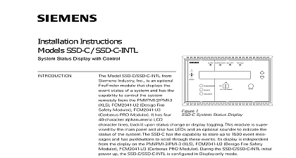
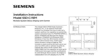
Siemens SSD SSD-INTL System Status Display, Installation Instructions

File Preview
Click below to download for free
Click below to download for free
File Data
| Name | siemens-ssd-ssd-intl-system-status-display-installation-instructions-6057214938.pdf |
|---|---|
| Type | |
| Size | 1.07 MB |
| Downloads |
Text Preview
TRAM 208 Multiplex Annunciator Panel Kenview Blvd Ontario T6L adanaC Industry Inc Fernwood Park 07932 U S A Rev 3 2013 of Contents TRAM 208 Remote Multiplex Annunciator Panel Wiring and Installation Manual 1 Instruction 2 Displays 2 Instruction 3 Switch Settings 4 Selection 4 Features 5 5 Specifications 5 Drain for Battery Calculations 5 Terms and Conditions of Sale 6 Remote Multiplex Annunciator Panel Wiring and Installation Manual TRAM 208 Annunciator is an 8 circuit annunciator for use with Siemen TXR 320 The annunciators into standard 4 gang electrical boxes and may not be expanded Control access is by a keyswitch Each Indicator is a bi colour LED that is automatically configured to match the Fire Alarm Control Panel For ULC S527 applications the TRAM 208 is an ancillary display device Instruction The TRAM 208 is supplied with NP 386 paper labels for zone identification This annunciator displays initiating circuit status only no individual circuit troubles Indicating and circuits are not remotely displayed For more details refer to the manual of the fire alarm control that the annunciator will be connected to The TRAM 208 has a keyswitch to enable the four slide switch controls The key should be secured Displays precise definitions of Control Display operation refer to the manual for the Fire Alarm Control Panel that the Annunciator is connected to Reset Signal Silence Silence Lamp Test On Common Trouble Signal Silence Circuit Status LED Remote Multiplex Annunciator Panel Wiring and Installation Manual Instruction RS 485 Wiring to the TRAM 208 Module is to be Twisted Shielded Pair as in the diagram The wire gauge may be AWG up to 2000 ft AWG up to 4000 ft AWG up to 8000 ft RS 485 wiring from the Fire Alarm Panel to the Annunciator s must be from the FA Panel to the first then the next Annunciator and on No star wiring or T tapping is allowed TRAM 208 Annunciator Module has a ohm End of Line Resistor on its RS 485 terminals This is removed on all the last wired Module 24 VDC field wiring needs to be of an gauge for the number of and the total wiring run length the specifications section Drain Battery Calculations and calculate the current for all Annunciators summed together Accidentally connecting any of the 24 VDC wires to the RS 485 wiring will result in damage to annunciator and or to the fire alarm control panel to which it is connected for all Wiring Run to Last Annunciator Loop Switch Settings annunciator needs to be assigned a unique sequential address via DIP switches SW1 1 SW1 2 and SW1 3 switch SW1 4 is used to allow disabling of some front panel slide switches digit address of the annunciator address 1 to 7 inclusive Address A0 Address A1 Address A2 SW1 4 is the System Reset and Signal Silence slide switches are disabled regardless of the operation of the keyswitch The Buzzer and Lamp Test slide switches will operate with the use of the SW1 4 is all four slide switches on the front panel will operate the use of the keyswitch the annunciator address see the manual for the fire alarm control panel being used as follows in the table DIP Switch Settings Annunciators on a common RS 485 connection must be numbered sequentially i e 1,2,3,4 and not such as 5,3,7 Note that not all Annunciator are valid for all Fire Alarm Control Panels to the Fire Alarm Control Panel Manual for further information Selection JP1 connects pins 1 and 2 and thus provides an eight bit checksum The eight bit checksum is used for Orange Wire Intact Buzzer silence Lamp Test local function only System Reset Signal Silence are disabled Jumper Orange Wire to have all remote functions operate Remote Multiplex Annunciator Panel Wiring and Installation Manual Features standard 4 gang Electrical Box is used Specifications VDC nominal voltage Controls LED indicators and Keyswitch to enable Controls Buzzer Indicators AC On Common Trouble Signal Silence and Controls Reset Lamp Test Buzzer Silence Signal Silence of up to 8 Points Expandable 35 mA Max All LED 90 mA Max Drain for Battery Calculations maximum normal current drain will be during Lamp Test when all lamps are illuminated on one chassis at a Thus the currents are as follows Standby Current 35 mA Current 90 mA Normal Standby Current is used for Battery Size Calculations see the Fire Alarm Control Panel manual and the current drain for the Trouble Buzzer Trouble LED and one Alarm LED The Maximum Current is to calculate the wire size see the Wiring Instruction Terms and Conditions of Sale Terms and Conditions of Sale following terms and conditions of sale shall apply to any sale of goods and services by Siemens Building Ltd hereinafter called Purchaser shall be deemed to have full knowledge of the terms conditions herein and such terms and conditions shall be binding if either the goods or services referred to are requested ordered or delivered to and accepted by Purchaser Alternatively if the Purchaser has not yet ordered or received the goods or services it shall be deemed to have accepted these terms and of sale unless Purchaser delivers to Siemens within five days from the date hereof written objection to terms and conditions or any part thereof Buyer issuance of a purchase order will constitute an acceptance of offer on the terms hereof and Buyer agrees that Buyer purchase order shall be for administrative purposes the event of any conflict or inconsistency between the terms and conditions of sale herein and the terms and contained in Purchaser order or in any other form issued by Purchaser whether or not any such form been acknowledged or accepted by Siemens Siemens terms and conditions herein shall prevail No waiver or modification of these term


