Siemens STRI-M Addressable Interface Module, Installation Instructions

File Preview
Click below to download for free
Click below to download for free
File Data
| Name | siemens-stri-m-addressable-interface-module-installation-instructions-9356421078.pdf |
|---|---|
| Type | |
| Size | 665.18 KB |
| Downloads |
Text Preview
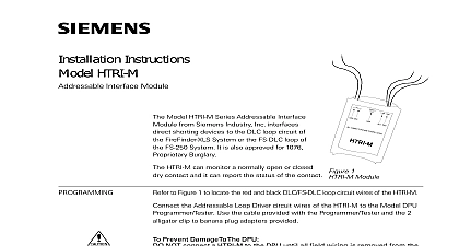
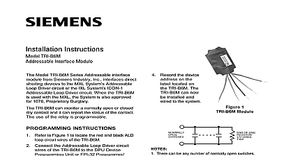
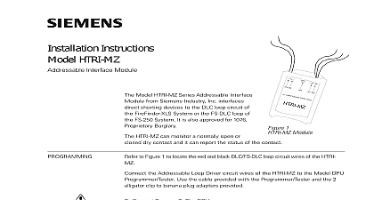
Installation Instructions STRI M Interface Module to Figure 1 to locate the red and black FDLC loop circuit wires of the STRI M Model STRI M Series Addressable Interface from Siemens Building Technologies Inc direct shorting devices to the FDLC loop of the FS 250C System STRI M can monitor a normally open or closed contact and it can report the status of the contact 1 Module LINE the Addressable Loop Driver circuit wires of the STRI M to the Model SDPU Use the cable provided with the Programmer Tester and the 2 clip to banana plug adapters provided Prevent Damage To The SDPU NOT connect a STRI M to the SDPU until all field wiring is removed from the and black FDLC loop circuit wires of the STRI M from the SDPU to the STRI M is not polarity sensitive Refer to 3 for the proper connections to the control panel to Figure 2 Follow the instructions in the SDPU Programmer Tester Manual 315 033260C to program the desired address into STRI M the device address on the label located on the STRI M The STRI M can now installed and wired to the system CLOSED OPEN NOTE 4 NOTES 2 AND 3 OF LINE OHMS OF LINE OHMS There can be any number of normally closed or normally open switches The end of line resistor must be located at the last switch Do not wire a normally closed switch across the end of line resistor Only for use with status applications 2 Switches 315 049480C 2 Building Technologies Safety to Figure 3 Refer to the wiring diagram and wire the addressable interface accordingly wire size AWG minimum AWG maximum SWITCH NOTES 1 AND 2 OHM OF LINE DEVICE NOTE 2 NOTE 5 2 1 2 1 FS 250C CONTROL PANEL LOOP DRIVER OR FROM PREVIOUS DEVICE NEXT DEVICE 3 the STRI M Wiring All supervised switches must be held closed and or open for at least a quarter of a second to guarantee detection End of line device 470 ohm 1 4W resistor P N 140 820164 Use Model EL 33 with 470 ohm 1 4W resistor STRI M is polarity insensitive Line 1 and Line 2 can be either line of the loop Addressable Loop Electrical ratings 24 VDC pulsing 31 VDC max maximum 1.3mA during polling The supervised switches have the following ratings VDC maximum maximum during polling resistance maximum 10 ohms cable length feet 18 AWG to line 0.02uF line size 14 AWG to shield line size 18 AWG 0.04uF shield ONLY at the specified location on the Control Panel device must be a 470 ohm 1 4 W resistor replacing an existing STRI on a device loop must also replace the EOL resistor if it is not ohms 1 4W The green wire must be connected to earth ground Use wire nuts to pass the shield wire through the electrical box with NO connection to the device green wire Use shielded wire to connect the switch wiring Tie the switch wiring shield to earth ground supervisory STRI M draws 1.3mA All circuits are power limited Positive and negative ground fault detected at 60K ohms for orange terminals Model STRI M mounts directly into a single gang switchbox user the appropriate wires using wire nuts Tuck STRI M module inside the electrical box and the wiring as required See Figure 4 SINGLEGANG SUPPLIED 4 the STRI M NOT REAR SUPPLIED 315 049480C 2 Building Technologies Ltd Kenview Boulevard Ontario L6T 5E4 Canada