Siemens SXL-AK Adapter Kit, Installation Instructions

File Preview
Click below to download for free
Click below to download for free
File Data
| Name | siemens-sxl-ak-adapter-kit-installation-instructions-2893150746.pdf |
|---|---|
| Type | |
| Size | 893.94 KB |
| Downloads |
Text Preview
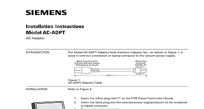
INTRODUCTION Instructions SXL AK Adapter Kit use with SXL BOX indoor use only in dry environments Model SXL AK from Siemens Industry is installed in an SXL BOX to enable the to be used with an SXL X Main and all optional modules following items are included in the package Adapter Plate New Door for the SXL BOX 6 6 32 x 1 11 16 Female Standoffs 2 8 32 x 1 11 16 Round Plastic Standoffs 3 8 32 x 11 16 Male Female Standoffs 2 6 32 x 11 16 Female Standoffs 7 8 Nuts 8 6 32 Screws 4 8 Flat washers Remove all system power before first battery and then AC Discard the mounting hardware from the kit with the SXL EX electronics Use the mounting hardware with the SXL AK kit Remove all components from the SXL BOX the three 8 32 x 11 16 male female on the studs marked A in the top of SXL BOX as shown in Figure 1 the two 6 32 x 11 16 female standoffs the studs marked B in the bottom of the as shown in Figure 1 the transformer P N 155 196118 and on the adapter plate as shown in 2 Mount the transformer on the studs in the left hand corner of the adapter plate shown in Figure 2 Secure in place using nuts and washers supplied Secure transformer leads through a tie wrap and secure it to the mounting stud The primary already have a wire clamp for strain 1 of Standoffs in SXL BOX Industry Inc Technologies Division Park NJ 315 096356 7 Building Technologies Ltd Safety Security Products Kenview Boulevard Ontario 5E4 Canada Mount the six metal 6 32 x 1 11 16 female Terminate the existing NAC wires to the 4 on the studs marked C on the plate as shown in Figure 2 Mount the two 8 32 x 1 11 16 round plastic on the studs in the center of the plate marked D as shown in Figure 2 Place the adapter plate in the SXL BOX by the three holes in the top of the plate the three standoffs marked A in the top of SXL BOX shown in Figure 3 Secure the plate in place with three 8 nuts at the and two 6 32 screws in the bottom of the plate Wire the Notification Appliance Circuits The wiring has been relocated in the SXL EX In order to use the existing wiring these steps terminals on the left side of the block on the adapter plate as in Figure 3 Attach the same size wire to the 4 screw on the right side of the terminal on the adapter plate as shown in 3 Make sure the wire is of sufficient to reach across the adapter plate the SXL X Main Board and up to on the SLX X Main Board If optional modules SLT 1 or SRC 8 are in the system these must be installed to the SXL EX board Install them in with the installation instructions the SXL EX System included with the module for x 1 11 16 Standoffs Places Plate for Optional or SRC 8 x 1 11 16 Plastic Places for Optional or SZE 8AX 2 of Studs on Adapter Plate addition when servicing these the SXL EX must be powered remove battery first then AC The board will have to be removed all field wiring in order to gain to the bottom screws when these modules Install the SXL X Main Board using the provided Refer to Figures 2 and 4 Fasten two of the screws provided in the bottom standoffs marked C shown in 2 leaving a 1 4 inch gap between standoff and the head of the screw Place the slots on the bottom of the Main board on the two screws Secure the board in place by fastening screws in the remaining standoffs C in Figure 2 If optional modules SZE 4X or SZE 8AX are in the system install them now in with the installation instructions the SXL EX System included with the modules Before connecting any wire to its screw refer to the Checkout Procedure in SXL EX Operation Installation and Manual P N 315 095997 Wiring compliance with UL 864 effective May 1 all power limited fire protective conductors must be separated a of 1 4 inch from all of the following located within a control panel electric light power Class 1 or non power limited fire signaling conductors Block NAC Wiring from Wires Reach from Block on Plate to TB7 SXL XMain Board Plate the Adapter Plate in the SXL BOX 3 meet these requirements the following guide must be observed when installing modules wiring to this control panel installing power limited field wiring the must comply with NEC article 760 54 states fire alarm power limited circuits are using Types FPL FPLR FPLP or substitute cable provided these cable conductors extending the jacket are separated by a of 0.25 in 6.35 mm or by a sleeve or nonconductive from all other conductors power wiring according to the SXL EX Installation and Maintenance P N 315 095997 Install the door supplied with the SXL AK Kit Reconnect the grounding strap as in Figure 5 4 5 the SXL X Main Board the Grounding Strap the Adapter Plate Industry Inc Technologies Division Park NJ 315 096356 7 Building Technologies Ltd Safety Security Products Kenview Boulevard Ontario 5E4 Canada