Siemens TRI-B6M Addressable Interface Module, Installation Instructions

File Preview
Click below to download for free
Click below to download for free
File Data
| Name | siemens-tri-b6m-addressable-interface-module-installation-instructions-6710284935.pdf |
|---|---|
| Type | |
| Size | 692.74 KB |
| Downloads |
Text Preview
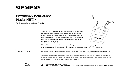
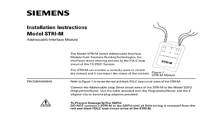
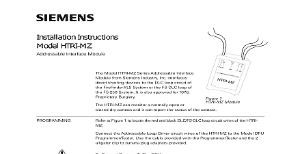
Installation Instructions TRI B6M Interface Module Model TRI B6M Series Addressable interface from Siemens Industry Inc interfaces direct devices to the MXL System Addressable Driver circuit or the IXL System ICON 1 Loop Driver circuit When the TRI B6M used with the MXL the System is also approved 1076 Proprietary Burglary TRI B6M can monitor a normally open or closed contact and it can report the status of the contact use of the relay is programmable INSTRUCTIONS Refer to Figure 1 to locate the red and black ALD circuit wires of the TRI B6M Connect the Addressable Loop Driver circuit of the TRI B6M to the DPU Device Unit or FPI 32 Programmer Use the cable provided with the and the 2 alligator clip to banana adapters provided TO PREVENT DAMAGE TO THE DO NOT connect a TRI B6M to the until all field wiring is removed from the and black ALD loop circuit wires of the TRI B6M Connection from the programmer to the is not polarity sensitive Refer to Figure 4 the proper connections to the control panel to Figures 2 and 3 Follow the instructions the DPU User Manual P N 315 033260 or the Programmer Tester Manual P N 315 to program the TRI B6M for the following Desired address Desired application for fire or proprietary security Normally open or normally closed switch Record the device on the located on TRI B6M The can now installed and to the system 1 Module OF LINE OHMS There can be any number of normally open switches The end of line resistor must be located at the last switch Do not wire a normally closed switch across the end of line In security applications an open or short causes a security 2 Normally Open Switches Industry Inc Technologies Division Park NJ 315 049485 3 Building Technologies Ltd Safety Security Products Kenview Boulevard Ontario 5E4 Ccnada CLOSED OF LINE OHMS 1 4W device must be a 470 ohm 1 4 W When replacing an existing TRI a device loop you must also replace EOL resistor if it is not 470 ohms 1 4W There can be any number of normally closed switches The end of line resistor must be located at the TRI An open causes a security alarm shield ONLY at the specified location the Control Panel Earth Ground is Available Normally Closed Switches Security Only 3 RATINGS Refer to Figure 4 to the wiring diagram and wire the addressable module accordingly Recommended wire size AWG minimum 14 AWG maximum The green wire must be connected to earth ground Use wire nuts to pass the shield wire through the electrical with NO connection to the device green wire Use shielded wire to connect the switch wiring Tie the switch wiring shield to the Addressable Loop circuit wiring shield Do not connect Addressable Driver circuit shield to earth ground Earth Ground is NOT Available the green wire to the Addressable Loop Driver circuit wire the Addressable Loop Driver circuit wiring is not the switch wiring and the Addressable Loop Driver wiring must be in conduit proprietary burglary application Refer to Figure 4 Use a TSW 1 2 tamper switch to monitor the main Monitor each TRI B6M related to this application by using a listed motion detector to prevent supervisory draws 1.8mA circuits are power limited to Figure 5 and negative ground fault detected at 40K ohms for terminals OHMS 1 4W Model TRI B6M mounts directly into a single switchbox user supplied the appropriate wires See Figure 4 using wire Tuck the TRI B6M module inside the electrical and dress the wiring as required 4 Wiring supervised switches must be held closed and or open for at a quarter of a second to guarantee detection of line device 470 ohms 1 4W resistor P N 140 820164 supervised switches have the following ratings maximum maximum resistance maximum cable length to line line size line size to shield 315 049485 3 VDC during polling ohms feet 18 AWG max 2.8 ohms max AWG AWG N O M X R P P R I C L I M I T M I B I N R G A R G D P O W E T T O I N A I C A M I N I O U T O D N 3 0 J R ll s N K DO NOT USE CONDUIT ENTRY GANG SUPPLIED GANG BLANK SUPPLIED 5 the TRI B6M


