Siemens TRI-S, TRI-D, TRI-R Addressable Interface Modules, Installation Instruction

File Preview
Click below to download for free
Click below to download for free
File Data
| Name | siemens-tri-s-tri-d-tri-r-addressable-interface-modules-installation-instruction-9852064713.pdf |
|---|---|
| Type | |
| Size | 733.42 KB |
| Downloads |
Text Preview
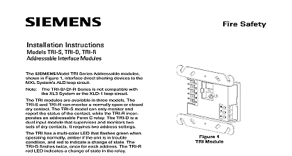
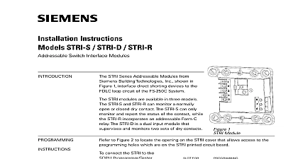
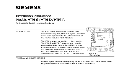
Installation Instructions TRI S TRI D TRI R Interface Modules Model TRI Series Addressable modules from Industry Inc shown in Figure 1 interface shorting devices to the MXL System s ALD loop The TRI S D R Series is not compatible with XL3 System or the XLD 1 loop circuit TRI modules are available in three models The and TRI R can monitor a normally open or closed contact The TRI S model can only monitor and the status of the contact while the TRI R incor an addressable Form C relay The TRI D is a input module that supervises and monitors two of dry contacts It requires two address settings TRI has a multi color LED that flashes green when normally amber if the unit is in trouble and red to indicate a change of state The flashes twice once for each address The TRI R LED indicates a change of state in the relay The of the relay is programmable INSTRUCTIONS Refer to Figure 2 to locate the openings on the TRI that allow access to the programming holes are on the TRI printed circuit board To connect the TRI to the DPU Device Programming or the FPI 32 Programmer Tester insert the from the cable provided with the programmer the opening on the front of the TRI Be sure to the locating tab on the plug into the slot for the tab on the TRI as shown in Figure 2 TO PREVENT DAMAGE TO THE DO NOT connect a TRI to programmer until at least one wire is from terminals 1 or 2 of the TRI 1 Module FOR TAB FROM FPI 32 Connection from the DPU or FPI 32 to the TRI is Refer to Figures 5 8 for the proper con to the control panel 2 the Programmer Tester Cable the TRI Module Industry Inc Technologies Division Park NJ 315 049481 5 Building Technologies Ltd Safety Security Products Kenview Boulevard Ontario 5E4 Canada to Figure 3 Follow the instructions in the User s Manual P N 315 033260 or the Programmer Tester Manual P N 315 to program the TRI to the following Desired address Desired application for fire or proprietary security Normally open or normally closed switch OF LINE OHMS There can be any number of normally open switches The end of line resistor must be located at the last switch Do not wire a normally closed switch across the end of line 3 Normally Open Switches LIMITED WIRING FOR TRI R INTERFACE MODULE compliance with NEC Article 760 all power limited protective signaling conductors must be separated minimum of 1 4 within an outlet box inch from all of the following items electric light power Class 1 or non power limited fire protective signal conductors meet the above the requirements the following must be observed when installing this module power limited wiring is not used within this box then the following guidelines do apply In that case be sure to follow wiring practices CONTROL MODULE BARRIER TRI R Control Module Barrier must be used when TRI R relay contacts are connected to non power lines Break apart the barrier to the correct size shape shown in Figure 4 for either the 4 inch or double gang box Install the barrier diagonally the backbox to create two separate compartments the backbox to separate the wires as shown in 4 GANG BOX 1 2 INCHES DEEP Record the device address on the label located on TRI front panel The TRI can now be installed wired to the system SQUARE BOX 1 8 INCHES DEEP OFF THIS WHEN A 4 INCH BOX OFF THIS WHEN A DOUBLE BOX the TRI R Control Module Barrier 4 RATINGS to Figures 4 8 to the appropriate wiring diagram below and wire addressable interface module accordingly Recommended wire size AWG minimum 14 AWG maximum larger than 14 AWG can damage the connector AND NEGATIVE FAULT DETECTED 40K OHMS FOR 3,4 CONTACTS NOTE 5 AND NEGATIVE FAULT DETECTED 40K OHMS FOR 3,4 USED AND NEGATIVE FAULT DETECTED 40K OHMS FOR 3,4 AND 6,7 USED OF LINE DEVICE NOTE 2 SWITCH NOTES 1 3 AND 4 ENTERING OUTLET BOX Limited Wiring power limited wiring must enter the outlet box from the electric light power Class 1 or limited fire protection signaling conduc For the TRI R wiring to terminal block positions 2 3 4 and 5 must enter the outlet box separately terminals 6 7 and 8 NEXT DEVICE MXL CONTROL PANEL FROM PREVIOUS DEVICE OF LINE DEVICE NOTE 2 SWITCH NOTES 1 AND 3 NOTES 6 AND 7 the length of wire entering the outlet box AT THE TERMINAL BLOCKS Limited Wiring Refer to Figure 5 to positions 1 2 3 4 and 5 is power limited Limited Wiring to positions 6 7 and 8 is considered non limited Remove all slack from these wires by pulling wiring back through the holes NEXT DEVICE MXL CONTROL PANEL FROM PREVIOUS DEVICE OF LINE DEVICE NOTE 2 SWITCH NOTES 1 AND 3 NOTES 6 AND 7 6 TRI R Wiring CONNECTED TO TERMINALS THROUGH 5 TO ENTER EXIT BOX OPPOSITE SIDE WIRES CONNECTED TO 6 THROUGH 8 POWER LIMITED NON POWER LIMITED 5 Power Limited Wiring of line device must be a 470 ohm 1 4W When replacing an existing TRI on device loop you must also replace the resistor if it is not 470 ohms 1 4W 7 TRI S Wiring NEXT DEVICE MXL CONTROL PANEL FROM PREVIOUS DEVICE OF LINE DEVICE NOTE 2 SWITCH NOTES 1 3 AND 4 NOTES 6 AND 7 8 TRI D Wiring The supervised switches have the following ratings maximum maximum resistance maximum 10 ohms cable length VDC during polling All supervised switches must be held closed and or for at least a quarter of a second to guarantee Use ULI listed EOL Model EL 30 31 mounting plate 470 ohm 1 4W resistor P N 140 820164 Order EL 30 31 separately to line to shield line size line size Cont feet 18 AWG max 2.8 ohms max AWG AWG Supervised switch S1 is on the first programmed and Supervised switch S2 is on the second address Relay contacts are rated 4A 125 VAC resistive 3.5A 120 VAC 0.6P F 30 VDC 0.6 P F 120 VAC 0.4 P F 120 VAC 0.35 P F 30 VDC 0.35 P F relay is shown in supervisory condition box with NO connection to the device block or to local ground Use shielded wire to connect the switch wiring to Tie the switch wiring shield to the ALD wiring Do not connect shield to terminal 5 or the earth ground a Good Local Earth Ground is NOT Available shield to terminal 5 ALD wiring is not shielded the switch wiring must in metal raceway 30 VDC resistive TRI shield wire ONLY at the specified on the Control Panel supervisory draws 1.8mA draws 2.3mA a Good Local Earth Ground is Available Terminal 5 must be connected to earth ground Use wire nuts to pass the shield wire through the 5 of the TRI S D R must be connected a known good earth ground for proper operation the electrical box the TRI is installed in is connect Terminal 5 to same Interface Models TRI S TRI D and TRI R directly into a user supplied double gang or 4 square electrical box Fasten the module to the box with the switchplate using the 2 screws Be sure to program the TRI before fastening switchplate to the unit SLOTS