Siemens VN2001-A1 Ethernet Module (10 100 BaseTx), Installation Instructions

File Preview
Click below to download for free
Click below to download for free
File Data
| Name | siemens-vn2001-a1-ethernet-module-10-100-basetx-installation-instructions-2439160785.pdf |
|---|---|
| Type | |
| Size | 1.06 MB |
| Downloads |
Text Preview
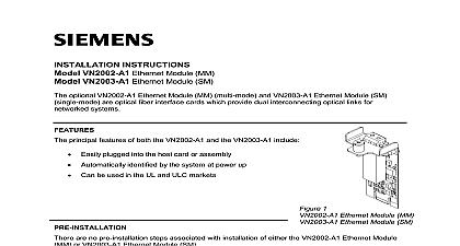
INSTRUCTIONS VN2001 A1 Ethernet Module 10 100 BaseTx optional Model VN2001 A1 Ethernet Module 10 100 BaseTx is an interface card which provides dual copper wire links for networked systems principal features of the VN2001 A1 10 100 BaseTx include easily plugged into the host card or assembly automatically identified by the system at power up Protects the Ethernet signal path from overvoltage caused by electrostatic ESD or electrical fast transients EFT Provides optimal ground fault detection user selectable Provides Power over Ethernet PoE 24V 500mA user Can be used in the UL and ULC markets 1 Ethernet Module BaseTx Determine from the site specific shop drawings whether the VN2001 A1 should be set for ground fault alone Power over Ethernet PoE plus ground fault supervision or neither function For ground fault supervision alone set the jumpers as illustrated in Figure 2a For Power over plus ground fault supervision set the jumpers as illustrated in Figure 2b If neither ground supervision nor PoE is required set the jumpers to the default setting as illustrated in Figure 2c Ground Fault Only Power over Ethernet and Open default setting Ground Fault 2 Settings 1 VN2001 A1 Ethernet Module 10 100 BaseTx can be used both in Voice networks of FV2025 2050 Voice Control Panels and in generic Ethernet systems in a Voice Network of FV2025 2050 Fire Voice Control Panels VN2001 A1 Ethernet Module 10 100 BaseTx is an optional card that plugs into the VCC Card Cage to an electrical interface for an Ethernet backbone network of FV2025 2050 Fire Voice Control Panels Figure 3 Each link in a Backbone is independently of any other link It can be implemented as either wire or fiber optic cable without any regard to what is used for the other links in the network For installation instructions applicable to fiber based links see Siemens Industry Inc Building Division document number A6V10370419 Installation Instructions for the Model Ethernet Module MM and the Model VN2003 A1 Ethernet Module SM backbone is a dual self healing redundant ring network that is able to detect failures and then isolate and recover from them using an alternate routing 3 Network Topology in a Voice Network of FV2025 2050 Panels in a Generic Ethernet Network addition to its use in an Ethernet backbone network of FV2025 2050 Fire Voice Control Panels as in Figure 3 the VN2001 A1 Ethernet Module 10 100 BaseTx can also be used to support copper connections among standalone FN2012 A1 Ethernet Switches modular two LEDs on the VN2001 A1 which are located at the copper cable connector indicate the following and Indicators Link established Signal activity 2 CARD CAGEVOICE CARD CAGEVOICE CARD CAGECOPPER FIBER ETHERNET BACKBONE NETWORKFV2025 2050 PANELFV2025 2050 PANELFV2025 2050 PANELVN2001 A1 10 100 BASE Tx OR VN2002 A1 MM ORVN2003 A1 SM ETHERNET MODULESfirealarmresources com the VN2001 A1 Ethernet Module 10 100 BaseTx in a Voice Network of FV2025 2050 Fire Control Panels Power down the Voice Panel before mounting the VN2001 A1 Open the middle door of the FV2025 2050 Fire Voice Control Panel Unscrew the latch on the front of the Card Cage and remove the Card Cage cover a VCC2001 A1 Voice CPU is installed in card slot X202 remove it If no VCC2001 A1 is proceed to the next step Referring to Figure 4 if the two knockouts for Ethernet modules are still present in the Card top panel remove them To avoid damage to sensitive electronic components remove burrs that may be present in the knockout opening the VCC2001 A1 Voice CPU card into card slot X202 according to instructions provided in Industry Inc Building Technologies Division document number A6V10397772 Instructions for the Model VCC2001 A1 Voice CPU Card FOR MODULES GUIDE CAGE TOP PANEL CAGE COVER GUIDE LATCH 4 knockouts for Ethernet Modules Refer to the site specific shop drawings to determine which position on the Voice CPU Card the is to be installed in the VN2001 A1 through the specified knockout opening on top of the VCA2002 A1 Card and carefully press it into the multi pin connector mounted on the VCC2001 A1 Voice card The multi pin connector is located approximately 21 2 below the knockout opening illustrated in Figure 5 Install the second module for the other link in the same manner the remaining knockout opening Tighten the fastening pin on the top of each module see Figure 5 by turning it clockwise until 3 modules are firmly held in place by the Card Cage it becomes necessary to deinstall the VCC2001 A1 Voice CPU Module first remove the modules that have been mounted on it MODULE MM or SM PIN ETHERNET 10 100 BaseTx CONNECTOR 5 Modules Installed in the VCA2002 A1 Card Cage Replace the Card Cage cover by re inserting it into the top of the Card Cage and sliding it until it reaches bottom Screw the cover latch back into the Card Cage cover the VN2001 A1 Ethernet Module 10 100 BaseTx in an FN2012 A1 Ethernet Switch Modular Remove the screws fastening the cover to the body of the FN2012 A1 Ethernet Switch and lift the cover off the assembly Please refer to Figure 6 If necessary remove one of the knockouts in the FN2012 A1 Ethernet modular side panel 4 PIN FOR MODULES ETHERNET MODULAR ETHERNET 10 100 BASE Tx FOR FASTENING PIN 6 the VN2001 A1 Ethernet Module in the FN2012 A1 Ethernet Switch the VN2001 A1 Ethernet Module 10 100 BaseTx through the knockout opening and press it into the multi pin connector mounted on the circuit card inside the switch body multi pin connector is located approximately 21 2 inches inside the opening Screw the fastening pin on the VN2001 A1 module into the mating hole in the side of the Ethernet Switch modular Replace the cover on the FN2012 A1 Ethernet Switch modular are no wiring operations for installing the VN2001 A1 onto the VCC2001 A1 Voice CPU card or an FN2012 A1 Ethernet Switch modular using the VN2001 A1 Ethernet Module 10 100 BaseTx to connect FV2025 2050 Panels consult site specific shop drawings for instructions on cabling FV2025 2050 Panels together to establish rings A single multi conductor cable is used to connect from one module to the next in the ring cable specifications are provided in Siemens Industry Inc Building Technologies Division number A6V10380472 Installation Instructions for the Model VCA2002 A1 Card Cage Table Cable Specifications 5 RATINGS Ethernet Module 10 100 BaseTx Power Requirements option no PoE 20 30VDC max PoE active 20 30VDC max max 6 page has been left intentionally blank 7 page has been left intentionally blank Industry Inc Technologies Division Park NJ Canada Limited Technologies Division Kenview Boulevard Ontario L6T 5E4 Canada ID A6V10370415 en a A5Q00054390 8