Siemens XND MNET HNET Network Interface, Installation Instructions

File Preview
Click below to download for free
Click below to download for free
File Data
| Name | siemens-xnd-mnet-hnet-network-interface-installation-instructions-5829073461.pdf |
|---|---|
| Type | |
| Size | 685.55 KB |
| Downloads |
Text Preview
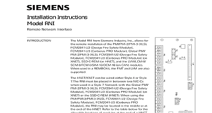
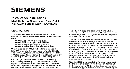
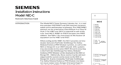
Installation Instructions XND Network Interface Model XND MNET Network Interface module from Industry Inc provides computers operating on 2000 or above with the capability to upload the Computer Software Generator program to an MXL The XND uses a USB connection to the computer XND has six LEDs to indicate the status of the module a reset button that can be used to restart the module case of malfunction Refer to Figure 1 to the CSG M Disk for XND Drivers and to the CSG M for XND Operation P N 315 049302 for informa regarding driver and software installation addition to the above application the XND can also be in a Fire Command Center or Building configuration of FVNET System where the XND is a FireFinder XLS interface module used to electrically connect to network via the RJ12 connector on a NIC C or PMI In this application the XND is the interface to the node HNET via the HNET NIC C It must be physically in the same cabinet as the HNET NIC C and the The XND is connected via USB to the VNT Refer to 2 and 3 all system power before installation first and then AC To power up connect the AC first the battery Connection Refer to Figure 1 one end of the USB cable supplied into the module labeled USB and the other end into a port on the pc the DB9 connector of the MXL programming cable the XND module labeled To Fire System and the 12 end into the MMB SMB to which the CSG M is to uploaded Connection Refer to Figures 2 and 3 The bracket for the XND is attached to the VNT MP Plate at the lower right hand corner is room to mount two XNDs in the bracket inserting the XND in the bracket make sure the XND is in the correct orientation for to the VNT The USB port should be out toward the Scalance X204 2 Ethernet Fiber Switch Refer to Figure 2 Tighten the nuts to secure the bracket in place Typical wiring for the XND in a VNT Building is shown in Figure 3 minimum firmware for the FVNET application is XND connection to the in the documentation and Figure 1 is as a temporary Tool upload the CSG M Software only is not UL approved for with the MXL Not Use MXL Programming DB9 here Button OPERATING INSTRUCTIONS 315 034731 Industry Inc Park New Jersey Top View USB Port here Not Use Y G 12 of MXL to MMB SMB Side View Side View 1 Connections PC Industry Inc Technologies Division Park NJ 315 034731 5 Canada Limited Technologies Division Kenview Boulevard Ontario L6T 7E4 Canada RATINGS connections are supervised and power limited stated otherwise Voltage 5V from USB Current 150mA Max BRACKET PORT X204 2 SWITCH RAIL 2 Mounting on VNT MP NOT USE NOT USE OF VNT NOT USE NOT USE NOT USE NOT USE NOT USE NOT USE NOT USE NOT USE NOT USE NOT USE 2 3 4 5 2 3 4 5 NOT USE NOT USE NOT USE NOT USE HNET OR XNET 2 P N 600 190704 P N 600 190704 FAIL FAIL FAIL FAULT 12A FAIL 4A FAIL X204 2 SWITCH O SYSTEM SYSTEM RJ12 RJ12 NOT USE NOT USE NOT USE NOT USE FROM VNT FROM VNT G 3 XND Wiring in a VNT Building Configuration 315 034731 5