Siemens XTRI-S XTRI-D XTRI-R Addressable Switch Interface Modules with Dual Isolators, Installation Instructions

File Preview
Click below to download for free
Click below to download for free
File Data
| Name | siemens-xtri-s-xtri-d-xtri-r-addressable-switch-interface-modules-with-dual-isolators-installation-instructions-9274610853.pdf |
|---|---|
| Type | |
| Size | 940.71 KB |
| Downloads |
Text Preview
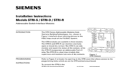
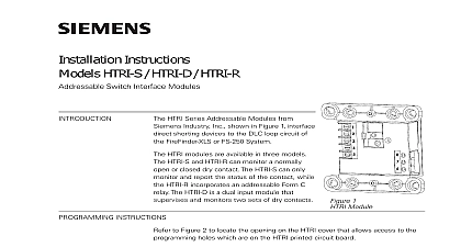
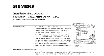
INSTRUCTIONS XTRI S XTRI D XTRI R Switch Interface Modules with Dual Isolators XTRI Series Addressable Modules from Siemens Industry Inc shown in Figure 1 interface direct devices to the device loop circuit of the Desigo FC2025 FC2050 FV2025 FV2050 and PRO FC922 FC924 FV922 FV924 Fire Alarm Systems Refer to the Configuration Tool ID A6V10315023 XTRI modules support two operation modes polarity insensitive mode and isolator mode The can be wired for either mode refer to Figures 8 through 13 During the isolator mode the built dual isolators will work at both sides of the module to isolate the line short in front or behind the XTRI modules are available in three models The XTRI S P N S54370 B3 A1 and XTRI R P N can monitor a normally open or closed dry contact The XTRI S can only monitor and the status of the contact while the XTRI R incorporates an addressable Form C relay The P N S54370 B2 A1 is a dual input module that supervises and monitors two sets of dry 1 Module Observe precautions for handling Electrostatic Sensitive Devices INSTRUCTIONS to Figure 2 to locate the opening on the XTRI cover that allows access to the programming holes are on the XTRI printed circuit board Siemens Industry Inc Building Technologies Division connect the XTRI to the DPU Programmer Tester insert the plug from the DPU cable provided with Programmer Tester into the opening on the front of the XTRI shown in Figure 2 The plug has no and can be inserted into the holes at either direction To prevent potential damage to the DPU DO NOT connect an XTRI to the DPU until all of the same polarity are removed from the device line of the XTRI the instructions in the DPU Manual P N 315 033260 to program the XTRI to the desired Record the device address on the address label which comes with the product and place it the module or on the XTRI front panel The XTRI can now be installed and wired to the system HOLES FOR IS NO FOR DPU IT ALLOWED TO THE PLUG EITHER DIRECTION FROM DPU 2 the DPU Plug SWITCHES AND EOL Deactivate P2 circuit by either or both of the following Using the PMI bypass the circuit modified and or physically disconnect the circuit from the P2 source CLOSED PROGRAMMABLE SWITCHES OPEN PROGRAMMABLE SWITCHES NOTES 1 3 AND 4 NOTES 1 AND 2 OF LINE OHMS 1 2W 3 Switches There can be any number of normally closed or normally open switches The end of line resistor must be located at the last switch Do not wire a normally closed switch across the end of line resistor Only for use with status applications OF LINE OHMS 1 2W CLOSED PROGRAMMABLE SWITCHES NOTES 1 3 4 AND 5 OPEN PROGRAMMABLE SWITCHES NOTES 1 2 3 4 AND 5 Supervision Resistor ohms 1 1 2W terminals Mount EOL on the TB EOL terminal The EOL resistor must be mounted at the last switch normally open switch TB EOL will not come with the package of product Use Siemens TB EOL P N S54322 F4 A2 or equivalent EOL 470 ohms 1 1 2W will come with the package of product For multi normally closed switches monitoring the open fault between switch will not be supervised Supervision Resistor ohms 1 1 2W 4 Wiring for Open Wiring Supervision 5 470 Ohms Resistor ohms 1 1 2W to Figures 6 and 13 Refer to the appropriate wiring diagram below and wire the addressable module accordingly wire size LIMITED WIRING compliance with NEC Article 760 all power limited fire protective signaling conductors must be a minimum of inch from all of the following items located within an outlet box AWG minimum AWG maximum larger than 14 AWG can damage the connector Electric light Power Class 1 or non power limited fire protective signaling conductors meet the above requirements the following guidelines must be observed when installing this module If power limited wiring is not used within this outlet box then these guidelines do not apply In case be sure to follow standard wiring practices CONTROL MODULE XTRI R Control Module Barrier must be used when the XTRI R relay contacts are connected to limited lines Break apart the barrier to the correct size and shape shown in Figure 6 for the 4 inch square or double gang box Install the barrier diagonally into the backbox to create two compartments within the backbox to separate the wires as shown in Figure 6 GANG BOX 1 2 INCHES DEEP SQUARE BOX 1 8 INCHES DEEP in in in in OFF THIS WHEN A 4 INCH BOX OFF THIS WHEN A DOUBLE BOX 6 the XTRI R Control Module Barrier ENTERING OUTLET BOX power limited wiring must enter the outlet box separately from the electric light power Class 1 or limited fire protection signaling conductors For the XTRI R wiring to terminal block 1 2 3 4 and 5 must enter the outlet box separately from terminals 6 7 and 8 Minimize the length of wire entering the outlet box AT THE TERMINAL BLOCKS Limited Wiring Refer to Figure 7 Wiring to positions 1 2 3 4 and 5 is power limited Limited Wiring Wiring to positions 6 7 and 8 is considered non power limited Ground shield of device line ONLY at the specified location on the Control Panel Non cable can be used for Input EOL device must be a 470 ohm 1 1 2W resistor for wire open supervision which comes the product CONNECTED TO TERMINALS THROUGH 5 TO ENTER EXIT BOX OPPOSITE SIDE WIRES CONNECTED TO 6 THROUGH 8 7 Power Limited Wiring POWER LIMITED NON POWER LIMITED All supervised switches must be held closed and or open for at least a quarter of a second to guarantee End of line device 470 ohm 1 1 2W resistor P N A5Q00073045 and use Model TB EOL with 470 ohm 1 1 2W For polarity insensitive wiring Line 1 and Line 2 can be either line of the device loop Supervised switch ratings feet 18 AWG maximum 27 VDC maximum 6mA during polling resistance maximum 10 ohms cable length to line line size 14 AWG to shield line size 14 AWG line size 18 AWG Relay contact ratings 125 VAC resistive 30 VDC resistive 120 VAC 0.6 P F 30 VDC 0.6 P F 120 VAC 0.4 P F 120 VAC 0.35 P F 30 VDC 0.35 P F relay is shown in standby condition the device line up to 30 of any compatible devices in polarity insensitive mode with 20 ohms max line resistance be isolated between two modules in isolator mode in a Class A Style 6 wiring the device line up to 30 of any compatible devices in polarity insensitive mode with 20 ohms max line resistance be isolated behind one module in isolator mode in a Class B Style 4 wiring HLIM isolator module and SBGA 34 sounder base cannot be used in the same loop with the modules in isolator 8 Polarity Insensitive Mode Wiring next device control panel previous device 1 2 1 2 monitored refer to 3 and 4 next device control panel previous device monitored refer to 3 and 4 Contacts Note 5 Contacts Note 5 9 Isolator Mode Wiring 10 Polarity Insensitive Mode Wiring next device control panel previous device 1 2 1 2 monitored refer to 3 and 4 next device control panel previous