Silent Knight 5128 5129 Four Channel Digital Communicator 4000

File Preview
Click below to download for free
Click below to download for free
File Data
| Name | silent-knight-5128-5129-four-channel-digital-communicator-4000-0259314876.pdf |
|---|---|
| Type | |
| Size | 1.13 MB |
| Downloads |
Text Preview
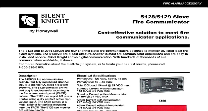
Silent Knight 5128 and 5129 Channel Digital Communicator AND ARCHITECT SPECIFICATIONS 864 Listed Meets NFPA 72 Chapter 4 for Central Station Remote Station Monitoring Listed as a Slave Communicator for Connection to System 3TM SXL IXL and MXL Fire Alarm Control Panels Four Fully Supervised Input Channels Dual Phone Line Interface and Line Fault Automatic 24 Hour Test Reports in Eight 8 Standard Communication Local Keypad Programmer Annunciator 5230 Remote Programming Up Down Loading Relay Output for System Alarm or Trouble Compact Size Allows Mounting in Most Cabinets also Available in Separate Model 5129 Features Pyrotronics offers the Silent Knight Models 5128 5129 four channel dual line digital communicators communicators are designed to monitor UL fire alarm control panels The model 5128 is specifi designed and listed to be mounted in the System 3TM IXL MXL system enclosures Power from these fire controls drive the 5128 and troubleshooting time is minimized by friendly English language messages available with the Model 5230 local programmer and PC based downloading software Model 5561 Inputs supervised or unsupervised channel inputs can be as either voltage inputs active high or low or contact closure inputs The System 3TM using CSI 35 module provides a combination of contact and active high voltage input to activate the 5128 The SXL IXL and MXL use a contact closure for each preset channels are programmed as follows 1 2 3 4 Fire Fire Supervisory Undefined Line Monitors phone line circuits detect phone line faults by monitor their voltages Reporting of a fault as a trouble condi is delayed by 40 90 seconds if the condition persists audible trouble in the communicator will sound and the reported to the central station To ensure phone line the 5128 and 5129 are equipped with line Functions power up the 5128 and 5129 self test system status watchdog circuit on the microprocessor resets the if a failure occurs Additionally a 24 hour test can be programmed to a central station at a time The installer can also initiate a manual test the Model 5230 programmer Model 5230 LCD keypad programmer can be tempo connected to program or troubleshoot the communi on site English language messages assist in data changing the 24 hour test time and describ conditions currently in effect A ring detector on the and 5129 allows one call downloading when used optional remote programming software and modem 5561 NUMBER Monitoring Models 5128 and 5129 transmit a distinct AC power trouble signal to the central station The Model 5128 this signal from the Cerberus Pyrotronics Fire Control Panel The SXL IXL and MXL transfer this via dry contact closure The System 3TM transmits signal via an active high output from the Model CSI 35 station interface 5129 5230 Cerberus Pyrotronics Fire Alarm Control Panels as well the Model 5128 and 5129 communicators can be to delay transmission of this signal to a station as required by Underwriters Laboratories the Model 5129 can monitor AC power through own transformer No AC signal transmission will then be from the fire alarm control Specification 24 VDC from UL fire control panel DC Load 84mA 154mA Monitoring Input Output Lights Formats trouble output from a alarm or System 3TM module or with 5129 VAC monitor transformer C at 1A 24 VDC 24 VAC Alarm or Trouble LED Power On LED Phone Line Trouble LED Input Fault and Trouble terminals for phone and relay outputs Color flying leads for control inputs via SK 3 1 4 2 SESCOA 3 1 SK 4 2 Radionics BFSK and 23 SIA 8 SIA20 Requirements FCC registration No Equivalence 0.9B of Jack RJ31X two 864 listed by Cerberus for use with SXL MXL and System 3TM 864 listed NYMEA and approved by Silent for Central Station Station Monitoring Specifications 5128 H x 4 W x 1 D meets UL94VO Lb H x 101 8 W x 3 D Metal Cabinet Lb with software modem kit interface kit includes block and cord 3 ft with connectors Suggestions System 3 mount in rear of enclosure or on rails SXL IXL mount on inside front door below viewing or left side backbox MXL mount on inside of MHD 2 or MSR 1 rail kit and Architect Specifications digital fire communicator shall be a Cerberus Pyrotron 5128 or 5129 and shall be installed in the fire control or mounted in a separate enclosure The slave shall be powered by 24 VDC from a UL fire alarm control and shall report four 4 conditions alarm 1 trouble 1 supervisory and 1 waterflow The unit shall have a built in auxiliary relay output is programmable for alarm or trouble conditions shall be capable of transmitting a distinctive AC power signal communicator shall have the following features visual audible trouble indications supervised or unsuper input channels dual phone line interface with line local and remote programming and automatic 24 test communicator shall be UL 864 listed and meet the of NFPA 72 Chapter 4 for supervising station alarm systems Information Number Knight 4 Channel Dual Digital Fire Communicator Knight 4 Channel Dual Digital Fire Communicator with Software Modem Interface Kit 3 Central Station Module 5128 5129 Wiring Information System 3TM Connection may be programmed for supervision if 5128 or 5129 is located outside enclosure Three 4.7K end of line resistors are provided with Model CSI 35 for supervision Additional alarm input may be connected to an auxiliary relay contact programmed for specific zone alarms i e duct Sprinkler supervisory input must be tied into ZN 34U2 for separate supervisory signal or relay contact on SR 32 program zone waterflow zone etc to activate from ZN 34U2 Suggested use to annunciate system or telephone line trouble from 5128 wire normally closed relay to unused zone on or ZU 35 with EOL device in series to open circuit or use relay to activate local 24 VDC audible trouble device See Installation Instruction P N 315 092318 SXL Connection may be programmed for supervision if 5128 or 5129 is located outside enclosure or if DFC 5129 is used Separate Watt resistors must be used if supervision is desired not supplied with 5128 29 Additional alarm input may be connected to an auxiliary relay contact programmed for specific zone alarms i e duct zone waterflow zone etc Suggested use to annunciate system or telephone line trouble from 5128 wire normally closed relay to unused zone on SZE 8A or on TB B6 of SXL main board with EOL device in series to open circuit or use relay to activate local 24 audible trouble device See Installation Instruction P N 315 093223 IXL Connection may be programmed for supervision if 5128 or 5129 is located outside enclosure or if DFC 5129 is used Separate Watt resistors must be used if supervision is desired not supplied with 5128 29 Additional alarm input may be connected to an auxiliary relay contact programmed for specific zone alarms i e duct zone waterflow zone etc Suggested use to annunciate system or telephone line trouble from 5128 or 5129 wire relay as shown to CZI L2S with device in series to open circuit when using the TRI B6 on IXL or MXL wire as shown an open or short will cause or use relay to activate local 24 VDC audible trouble device See Installation Instruction P N 315 093301 MXL Connection may be programmed for supervision if 5128 or 5129 is located outside enclosure or if DFC 5129 is used Separate