Silent Knight IDP6ab isheet

File Preview
Click below to download for free
Click below to download for free
File Data
| Name | silent-knight-idp6ab-isheet-5804179326.pdf |
|---|---|
| Type | |
| Size | 670.55 KB |
| Downloads |
Text Preview
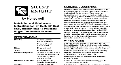
FUNCTION REMOTE ANNUNCIATOR ANNUNCIATOR TERMINALS detector base mounts directly to 3 1 2 inch and 4 octagon boxes 4 inch square boxes with or without rings and single gang boxes To mount remove ring by turning it in either direction to unhook snaps then separate the ring from the base Install base to the box using the screws supplied with the box and the appropriate mounting slots in the Place decorative ring onto base then turn in either until the ring snaps in place see Figure 2 PROOF 1 Terminal Layout Plug in Detector Installation Instructions inches 15.5 cm square box 102 mm or without plaster ring Depth 1.5 inches 4 inch 102 mm Box Min Depth inches 38 mm 3 1 2 89 mm Octagon Box Depth 1.5 inches 38 Single Gang Box Min 1.5 inches 38 mm Temperature DESCRIPTION IDP 6AB base is a plug in detector base intended for in a 2 wire intelligent system with screw terminals for power and and remote annunciator Communication takes place over the power and lines to 150 0 to 66 RATINGS includes Base and Detector Range Current Surge At Rated Voltage Current 32 Volts DC Peak at 24 VDC mA sec mA at 24 VDC WIRING wiring must be installed in compliance with the Electrical Code and all applicable local codes any special requirements of the authority having using the proper wire size The conductors to connect smoke detectors to control panels and devices should be color coded to reduce the of wiring errors Improper connections can a system from responding properly in the event a fire signal wiring the wiring between interconnected it is recommended that the wire be no smaller AWG 18 However the screws and clamping plate in base can accommodate wire sizes up to AWG 12 The of twisted pair wiring or shielded cable for the power and loop is recommended to minimize the effects of interference shielded cable is used the shield connection to and the detector must be continuous by using wire crimping or soldering as appropriate for a reliable connections are made by stripping about 3 8 of from the end of the wire use strip gauge in base sliding the bare end of the wire under clamping plate and tightening the clamping plate Do not loop the wire under the clamping plate zone wiring of the detector base should be checked the detector heads are installed in them The should be checked for continuity and polarity in base and dielectric tests should be performed base contains a label to write the zone address type of detector to be installed at that location This is important to set the address of the detector that will later be plugged into the base and to verify type required for that location Do NOT use the tamper resistant capability if the or XR2B Removal Tool will be used Tamper Resistant Tab in the Detector Mounting can make the detector tamper resistant by it necessary to use a small screwdriver or similar to detach the detector from the base make the detector tamper resistant use needle nose to break the smaller tab at the scribed line on the resistant tab Figure 1 shows the location of this on the detector mounting bracket remove the detector from the base after it has been tamper resistant remove the decorative ring by it in either direction and pulling it away from base Then insert a small screwdriver into the notch indicated in Figure 4B and press the plastic lever the mounting surface before rotating the detector for removal ON NOT NOT 2 Mounting Detector to Box ANNUNCIATOR Do not loop wire under terminal 1 or 2 wire run to provide supervision of connections A OPTIONAL WIRING 3 Typical Wiring Diagram for 2 wire loop LEVER TAB AT LINE BY TOWARD OF BASE SMALL BLADED TO PLASTIC LEVER DIRECTION OF 4A Enabling the Capability 4B Removing the Detector from the Base ANNUNCIATOR MODEL RA400Z remote annunciator is connected between terminals 1 and 3 using the spade lug terminal packed with the remote The spade lug terminal is connected to the base terminal as shown in Figure 5 is not acceptable for three stripped wires to be under the same wiring terminal unless they are separated by a washer equivalent means The spade lug supplied with the model RA400Z is considered an equivalent means See Figure 5 proper installation WIRE WITH LUG 5 Connection to Remote Annunciator Terminal Meridian Circle Grove MN 55369 4927 800 328 0103 763 493 6475 2005 Silent Knight refer to insert for the Limitations of Fire Alarm Systems