Silent Knight IDPbeamT isheet

File Preview
Click below to download for free
Click below to download for free
File Data
| Name | silent-knight-idpbeamt-isheet-6019425783.pdf |
|---|---|
| Type | |
| Size | 1.30 MB |
| Downloads |
Text Preview
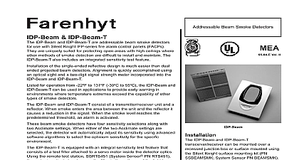
INSTALLATION AND INSTRUCTIONS IDP Beam T Single ended Type Projected Beam Smoke Detector Time Conditions Features 7 Operation Weight Size Angle Trim Ring to 230 Feet 5 to 70m to 328 Feet 70 to 100m using optional accessory BEAMLRK to 50 Total Obscuration in 6 levels 1 25 2 30 3 40 4 50 5 30 to 50 Acclimate 6 40 to 50 Acclimate to 60 Feet 9.1 to 18.3m 20 seconds typical 30 seconds typical Blockage 96 or More Obscuration Initial Alignment limit reached service needed Alignment mode Sensitivity Test Filter IDP Beam T only requires additional external power supply Filter Incremental scale on reflector Alarm Test Switch Alarm Reset Switch Test and Reset Switch Capability with RTS451 RTS451KEY Operation Aids isolators provide style 7 operation may be disabled via shunts on circuit board Output Local LED red Output Local LED yellow Pattern Indicates Trouble Diagnostics LED flashing green with communication Gunsight coarse adjustment to 99 Digital Display fine adjustment Display Readout in Percent Obscuration to 131 to 55 for applications below 32 0 see Special Applications section of this manual to 93 RH Noncondensing lbs 1.77 kg 10.5 6.5 381mm 267mm 165mm only without optional accessories Terminal Blocks 12 to 22AWG Horizontal and Vertical be painted using enamel or acrylic type paints Current Supply IDP Beam T only Output to 32 VDC Standby communication every 5 sec LED flashing SLC 24 V Alarm LED on Trouble LED on Alignment Max Max Max Max to 32 VDC Max to 32 VDC Output voltage same as device input voltage maximum minimum Output current is limited by 2.2Kohm resistor Description IDP Beam IDP Beam T is a long range projected smoke detector designed to provide open area It is to be used with UL listed compatible panels only The detector consists of a transmitter unit and a reflector Smoke entering the area the transmitter receiver and reflector causes a in signal When the obscuration reaches alarm chosen at the transmitter receiver unit the generates an alarm signal Complete blockage the beam causes a trouble signal Slow changes in due to a build up of dirt or dust on the lens of detector are compensated for by a microcontroller that monitors the signal strength and periodically the alarm and trouble thresholds When the circuit reaches its limit the detector a trouble signal indicating the need for service LEDs on the detector indicate the current status red LED for alarm a yellow LED for trouble and a green LED for standby operation Note The controls the status of the red and green LEDs The reset button is accessible by removing the outer trim ring The yellow LED will blink in specific to provide a diagnostic aid when diagnosing the of a trouble signal It will also blink the amount of compensation that has been used at the conclusion the test Trouble signals automatically reset upon the cause of trouble Red and yellow LEDs be remotely connected to the remote Alarm and outputs These outputs mimic the functions of detector red and yellow LEDs In addition to these there is a dual digital display that reads 00 to This display is used to indicate the signal strength the beam in alignment mode and to indicate the setting of the detector in percent obscuration setting the sensitivity of the detector No additional is needed for alignment of the beam Applications to the inherent capabilities of projected type beam they are often installed in locations where detection is impractical Projected type beam detectors are ideally suited for environmental that might include high ceilings dusty and dirty or environments that experience temperature Often these conditions present special problems the installation of spot type detectors and even greater for their proper maintenance Due to the inherent of mounting locations and large coverage area of type beam detectors often the conditions above be addressed or minimized examples of applications for beam detectors include freezers aircraft hangars cold storage shipping warehouses enclosed parking sporting arenas and stadiums concert halls or stables Some of these environments might be too hostile for spot type smoke detectors the environment is considered to be hostile then the alarm threshold settings should be used installing the transmitter receiver unit or reflector these types of applications special consideration be given to insure proper operation of the beam The beam detector should not be installed in where there is no temperature control condensation or icing is likely Condensation or of the reflector surface or the outer surface of the unit will obscure the light beam in a false alarm If elevated humidity levels rapidly changing temperatures can be expected then will likely form and the application should be considered acceptable for the beam detector Accessories following accessories can be purchased separately use with this beam detector BEAMLRK allows Silent Knight reflected beam to be installed at separations between 230 and feet 70 to 100 meters At these distances four 8 8 must be used to provide enough reflected infrared This kit includes 3 additional reflectors with new test legends The reflector included with the transmitter unit is the fourth reflector to be used This kit is not with the multi mount kit BEAMMMK BEAMMMK allows Silent Knight reflected beam and reflectors to be mounted to either a wall or the ceiling The kit allows for additional range in cases where the detector and reflector be mounted within 10 of each other The kit the hardware necessary to mount either a transmitter receiver unit or a single reflector mount the transmitter receiver the surface mount BEAMSMK must also be used If the transmitter and the reflector require additional alignment two kits are required The kit is not compatible the long range reflector kit BEAMLRK BEAMSMK allows Silent Knight reflected beam to be mounted when surface wiring is used kit must be used when mounting the transmitter unit with the multi mount kit BEAMMMK BEAMHK allows the transmitter receiver unit operate in environments prone to the formation of Condensation forming on the beam detector may result in trouble or false alarm conditions will lessen the likelihood of condensation by the unit at a temperature that is slightly higher the surrounding air Please refer to the BEAMHK manual for operation instructions BEAMHKR allows the reflector to operate in prone to the formation of condensation forming on the reflector may result in or false alarm conditions BEAMHKR will the likelihood of condensation by maintaining reflector at a temperature that is slightly higher surrounding air The kit requires a 24V power When used with the long range reflector kit it is necessary to purchase and install BEAMHKR kits Please refer to the BEAMHKR manual for operation instructions remote test accessory RTS451 KEY allows for the detector to be tested remotely The test accessory test and reset functions and green and red LED mimic the LEDs on the detector List Unit 1 Trim Ring 1