Silent Knight RA2000is

File Preview
Click below to download for free
Click below to download for free
File Data
| Name | silent-knight-ra2000is-9207358146.pdf |
|---|---|
| Type | |
| Size | 1.03 MB |
| Downloads |
Text Preview
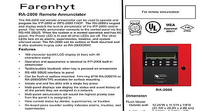
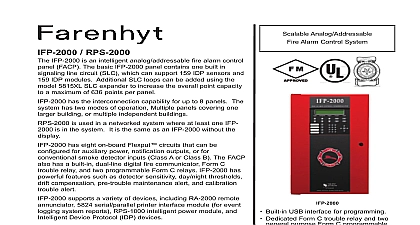
RA 2000 Remote Annunciator optional Model RA 2000 Remote Annunciator shown in 1 performs the same functions as the on board Operation is identical The RA 2000 can be surface flush monted to 8 RA 2000s can be added to the IFP 2000 system Voltage VDC mA mA Temperature 0 to 49 C 32 to 120 F 12 1 4 W x 11.5 H x 7 8 D cm W x 29.2 cm H x 2.2 cm D Mounting for back box trim ring W x 11.5 H x 3 D cm W x 29.2 cm H x 7.6 cm D the RA 2000 section of the manual describes mounting the remote The annunciator can be flush or surface mounted Mounting section of the manual describes flush mounting these steps to flush mount the RA 2000 back box dimensions are 9 3 8 w x 8 3 8 h The depth 2 The back box can be mounted prior to complete installation of the RA 2000 using any of the holes shown in Figure 3 Holes 1 Model RA 2000 Remote Annunciator installation involves the following steps Make sure power is off at the panel Mount the RA 2000 in the desired location see Section the RA 2000 Connect the RA 2000 to the panel see Figure 2 Use the dipswitches on the back of the RA 2000 to assign ID to the RA 2000 see Section 4.10.1 of Manual P N RA 2000 module must be added to the system through JumpStart AutoProgramming will add the automatically refer to Manual P N 151430 Connections the RA 2000 to the FACP as Shown in Figure 2 Holes 3 Back Box Mounting Holes Remove knockout holes as needed for wires See Figure 4 2 SBUS Connections RA 2000 Installation Instructions backbox knockout locations level insert the rest of the mounting screws Knockouts Shaped Hole Knockouts Box Holes Knockouts 4 Back Box Knockout Locations Wire the Annunciator board to the main control panel See 2 Attach the annunciator and door assembly to back box as in Figure 5 using the supplied screws 6 Back Box Surface Mount Holes Run wires to the control panel the trim ring over the back box as shown in Figure 7 5 Attaching Annunciator Door Assembly to Mounting Model RA 2000TG TR trim ring kit is available for use surface mounting Remove the desired knock out See Figure 4 properly mount the back box insert a single screw into key shaped mounting hole Do not tighten all the way Figure 6 a level on top of the back box with the back 7 Installing Trim Ring Attach the Door assembly to the back box using screws After the annunciator wiring to the panel has been replace the electronic assembly in the back box the bezel over the back box and tighten the set screws the bezel Meridian Circle Suite 100 Grove MN 55369 4927 or 800 328 0103 763 493 6475 2008 Honeywell International Inc 151443 Rev A