System Sensor Silent Knight IDPssb224rb isheet

File Preview
Click below to download for free
Click below to download for free
File Data
| Name | system-sensor-silent-knight-idpssb224rb-isheet-4269301785.pdf |
|---|---|
| Type | |
| Size | 631.35 KB |
| Downloads |
Text Preview
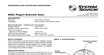
INSTALLATION AND MAINTENANCE INSTRUCTIONS Plug in Detector Base Diameter Height Ohio Avenue St Charles Illinois 60174 FAX 630 377 6495 inches 155 mm inches 31 mm square box with or without plaster ring Min Depth 1.5 inches 38 mm octagon box Min depth 1.5 inches 38 mm octagon box Min depth 1.5 inches 38 mm to 49 32 to 120 to 93 Relative Humidity Non condensing Temperature Range Humidity Range Ratings Voltage Averaged Standby Ratings 500 24 VDC Characteristics to 32 VDC Type Relay coil latching Form C A 30 VDC A 110 VDC with 35 PF or greater A 120 VAC with 35 PF or greater A 30 VDC with 6 PF or greater seconds minimum 20 seconds maximum second minimum 8 seconds maximum Time Time Installing thoroughly read the system wiring and installation and the System Smoke Detectors Applications which provide detailed information on detector placement zoning and special applications This manual should be left with the owner user this equipment The detector used with these bases must be and maintained regularly following NFPA 72 require The detectors should be cleaned at least once a year Information C latching relay contacts are included for the control an auxiliary function The relay operates 12 seconds after activation of the sensor head remote output detector base mounts directly to 31 and 4 inch octa and 4 inch square boxes with or without a plaster ring mount remove the decorative ring by rotating it in either to unhook the snaps Then separate the ring from base Install the base on the box using the screws sup with the junction box and the appropriate slots in the Replace the decorative ring on the base and rotate it in direction until the ring snaps in place see Figure 1 Guidelines wiring must be installed in compliance with all appli local codes and any special requirements of the local having jurisdiction using the proper wire sizes conductors used to connect smoke detectors to control and accessory devices should be color coded to the likelihood of wiring errors Improper connec can prevent a system from responding properly in the of a fire signal wiring the wiring between interconnected it is recommended that the wire be no smaller 18 gauge 0.9 square mm However wire sizes up to gauge 2.0 square mm can be used with the base The of twisted pair wiring or shielded cable for the power and loop is recommended to minimize the effects of interference shielded cable is used the shield connection to and from detector must be continuous by using wire nuts crimp or soldering as appropriate for a reliable connection system control panels have specifications for allow loop resistance Consult the control panel specifica for the total loop resistance allowed before wiring the loops Instructions base uses a latching relay that can change states if it is to mechanical shocks or jarring As a result even relay contacts are in the open state when the base shipped from the factory the contacts may have closed shipment an auxiliary control circuit to closed relay con can cause an unexpected and possibly dangerous of that circuit Therefore do NOT connect an control circuit to the relay contacts terminals 1 and 3 before ensuring that the relay contacts are in their state Ensure that the contacts are open by applying to the bases WITHOUT the sensor heads installed wiring connections by stripping about 3 10 mm of from the end of the wire Then slide the wire the clamping plate and tighten the clamping plate 1 Mounting the base to an electrical box ON NOT NOT the normally open NO line to terminal 2 see Figure Insert the normally closed NC line of the relay to ter 1 and the relay common line to terminal 3 Wire the lines in and out to terminal 4 the communication line in and out to terminal Terminal 6 is for shielded cable only see Figure 2 If cable is used the shield connection to and from the must be continuous by using wire nuts crimping soldering to ensure a reliable connection If shielded is not used leave terminal 6 in the screwed down the zone wiring of all bases in the system before detector heads This includes checking the wiring continuity correct polarity ground fault testing and a dielectric test 2 Wiring diagram PAIR RECOMMENDED INTELLIGENT RELAY COMMON NORMALLY CLOSED NORMALLY OPEN A OPTIONAL WIRING label is affixed to the base for recording the zone and type of detector being installed at the base This information is useful for setting the detector address and for verification of the sensor type for that location all detector bases have been wired and mounted and loop wiring has been checked the detector heads may installed in the bases Feature Do not use the tamper resist feature if the removal is to be used detector base includes a tamper resist feature that pre its removal from the base without the use of a tool activate this feature break the tab from the detector as shown in Figure 3A see page 4 Then install the remove the detector from the base once the tamper feature has been activated insert a small bladed into the slot in the side of the base and push plastic lever away from the detector head see Figure page 4 This allows the detector to be rotated counter for removal Head removal after the tamper resist feature has activated first requires removal of the decora ring tamper resist feature can be defeated by breaking and the plastic lever from the base However this the feature from being used again 3A Activating the tamper resist feature 3B Removing the detector head from the LEVER TAB AT LINE BY TOWARD OF BASE SMALL BLADED TO PLASTIC LEVER DIRECTION OF refer to insert for the Limitations of Fire Alarm Systems Limited Warranty Sensor warrants its enclosed smoke detector base to be free from in materials and workmanship under normal use and service for a of three years from date of manufacture System Sensor makes no express warranty for this smoke detector base No agent representa dealer or employee of the Company has the authority to increase or the obligations or limitations of this Warranty The Company obli of this Warranty shall be limited to the repair or replacement of any of the smoke detector base which is found to be defective in materi or workmanship under normal use and service during the three year commencing with the date of manufacture After phoning System toll free number 800 SENSOR2 736 7672 for a Return number send defective units postage prepaid to System Repair Department RA 3825 Ohio Avenue St IL 60174 Please include a note describing the malfunction and cause of failure The Company shall not be obligated to repair or units which are found to be defective because of damage unrea use modifications or alterations occurring after the date of man In no case shall the Company be liable for any consequential or damages for breach of this or any other Warranty expressed or whatsoever even if the loss or damage is caused by the Company or fault Some states do not allow the exclusion or limitation of or consequential damages so the above limitation or exclusion not apply to you This Warranty gives you specific legal rights and may also have other rights which vary from