Simplex 4098-9687 Stand Alone Duct Detector Installation Instructions

File Preview
Click below to download for free
Click below to download for free
File Data
| Name | simplex-4098-9687-stand-alone-duct-detector-installation-instructions-2350198746.pdf |
|---|---|
| Type | |
| Size | 1.23 MB |
| Downloads |
Text Preview
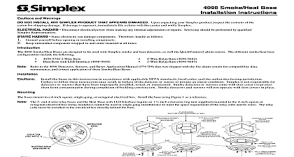
4098 9687 Stand Alone Duct Detector Instructions B Page DEVICE IS A STAND ALONE DUCT DETECTOR IT IS DESIGNED SAMPLE THE AIR FLOW PASSING BY IT IN THE AIR DUCT TO WHETHER IT CONTAINS UNACCEPTABLE LEVELS OF EFFECTIVENESS OF A STAND ALONE DUCT DETECTOR IS DEPENDENT UPON THE DESIGN AND OPERATING CONDITIONS OF THE AIR HANDLING IN WHICH IT IS INSTALLED VARIABLES SUCH AS SMOKE DILUTION AND STRATIFICATION OVER EVEN THE BEST DESIGNED SYSTEMS HAVE NO CONTROL PROPER PLACEMENT AND POSITIONING OF THE STAND ALONE OFTEN COMPROMISED FOR DETECTOR WHICH REASONS THE REASONS STATED ABOVE THE EFFECTIVENESS OF THE ALONE DUCT DETECTOR CANNOT BE WARRANTEED OR UNDER NO CIRCUMSTANCES SHOULD THIS STAND DUCT DETECTOR BE USED AS OR REGARDED TO BE A FOR THE BUILDING REGULAR FIRE ALARM AND SYSTEM NFPA STATES THAT DUCT SMOKE DETECTORS MUST NOT BE AS SUBSTITUTES FOR OPEN AREA PROTECTION DO NOT THE STAND ALONE DUCT DETECTOR TO A FIRE ALARM PANEL THIS UNIT IS INTENDED AS A STAND ALONE DEVICE USE IN THE CONTROL OF AIR HANDLING EQUIPMENT FOR THE OF CLOSING DAMPERS OR SHUTTING DOWN AIR UNITS Page of Contents of Contents iii Description 1 Specifications 3 Stand Alone Duct Detector Housing 3 Duct Control Station 6 Routines 8 to Follow 8 Alone Duct Detector Installation 10 Procedures 12 Installation 13 Replacement 14 or DC Operation Detector Testing 14 Air Test 14 Test for Photoelectric Detectors 15 Method of Testing Smoke Detectors Sensors 16 Differential Pressure Test 17 or following an 8 digit Product ID number denotes ULC listed product Simplex Time Recorder Company Westminster MA 01441 0001 U S A Simplex International Time Equipment Co Ltd Mississauga Ontario L4V 1H3 Canada specifications and other information shown were current as of publication and are subject to change without notice PAGE Page Description 4098 9687 Stand Alone Duct Detector see Figure 1 on page 2 is designed sample air and detect smoke in air ducts The 4098 9687 duct detector uses 4098 9601 photoelectric smoke detector 4098 9687 Stand Alone Duct Detector provides fail safe operation the loss power or detector removal activates the Duct Detector Housing alarm relay 4098 9842 Duct Control Station see page 6 for details is the remote interface connected to the Stand Alone Duct Detector and provides a LED Alarm LED audible sounder sounder silence switch and Test Reset switch detailed information on using smoke detectors in air distribution systems see 90A and refer to the following excerpt from NFPA 90A NFPA 90A 1999 Edition 4 4.4.3 Where smoke detectors required by Section 4 4 are installed in building not equipped with an approved fire alarm system as by 4 4.4.2 the following shall occur Smoke detector activation required by Section 4 4 shall cause a visual and signal in a normally occupied area Smoke detector trouble conditions shall be indicated visually or audibly in a occupied area and shall be identified as air duct detector trouble on next page Description Continued BASE GASKET GASKET LED DETECTOR MAGNETIC LOCATION CAPTIVE PANHEAD 4 PLUG GROUP 748 518 NOTE CONDUIT ENTRY 12 18 AWG WIRE MAGNET HERE TEST COVER PORT AIR FLOW HOLES BASE ASSEMBLY Two 3 4 conduit entries are provided for field wiring 12 18 AWG to the PCB assembly The conduit entry is sealed off using the cap plug group 748 518 Apply even pressure on the cap plug to secure it against the conduit plate cap plug seals and removes easily with moderate 1 Stand Alone Duct Detector Components Specifications Stand Alone Duct Housing 4098 9687 Stand Alone Duct Detector can be powered from 24 VDC 24 VAC or VAC power sources Separate terminal block connections are available for the VDC VAC or the 120 VAC power sources When the 120 VAC connection is used connections should be made to the 24 VDC VAC inputs The power sources must originate from a fused power supply listed for fire signaling use or from the Fire Alarm Control Panel FACP power Listed below are the electrical specifications for the 4098 9687 Stand Alone Duct configurations 24 VDC Power Operation Figure 2 Page 4 Voltage 20.4 to 32 VDC Current 40 mA at 24 VDC maximum Alarm Current 50 mA at 24 VDC maximum Control Contacts Alarm Relay Dry SPDT N O TB2 1 K1 C TB2 2 K1 N C TB2 3 relay contacts rated 5 amp at 24 VDC VAC or 120 VAC resistive 24 VAC Power Operation Figure 2 Page 4 Voltage 20.4 to 32VAC Current 100 mA at 24 VAC maximum Alarm Current 125 mA at 24 VAC maximum Control Contacts Alarm Relay Dry SPDT N O TB2 1 K1 C TB2 2 K1 N C TB2 3 120 VAC Power Operation Figure 3 Page 5 Voltage 102 to 132 VAC 60Hz Current 30 mA at 120 VAC maximum Alarm Current 40 mA at 120 VAC maximum Control Contacts Alarm Relay Dry SPDT N O TB2 1 K1 C TB2 2 K1 N C TB2 3 Note Note Note relay contacts rated 5 amp at 24 VDC VAC or 120 VAC resistive relay contacts rated 5 amp at 24 VDC VAC or 120 VAC resistive Continued on next page Electrical Specifications Continued ALONE DETECTOR