Simplex 4098-9788 Smoke Detector Base Installation Instructions

File Preview
Click below to download for free
Click below to download for free
File Data
| Name | simplex-4098-9788-smoke-detector-base-installation-instructions-1208476539.pdf |
|---|---|
| Type | |
| Size | 1006.46 KB |
| Downloads |
Text Preview
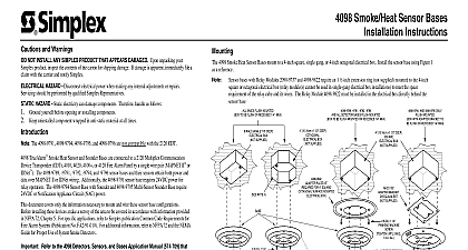
Smoke Heat Base Instructions and Warnings NOT INSTALL ANY SIMPLEX PRODUCT THAT APPEARS DAMAGED Upon unpacking your Simplex product inspect the contents of the for shipping damage If damage is apparent immediately file a claim with the carrier and notify Simplex HAZARD Disconnect electrical power when making any internal adjustments or repairs Servicing should be performed by qualified Representatives HAZARD Static electricity can damage components Therefore handle as follows Ground yourself before opening or installing components Keep uninstalled component wrapped in anti static material at all times 4098 Smoke Heat Bases are designed to be used with Simplex smoke and heat detectors as well the QuickConnect2 photo sensor The different smoke heat base include the following 2 Wire Base Base with LED Interface 4098 9684 Relay Base 4098 9682 Relay Base 4098 9683 Refer to the 4098 Detectors Sensors and Bases Application Manual 574 709 that was shipped with the fire alarm system for compatibility data and correct application of these Smoke Heat Bases the bases in this instruction in accordance with applicable NFPA standards local codes and the authorities having jurisdiction to follow these instructions may result in failure of the detector or sensor to initiate an alarm condition Simplex is not responsible for or sensors that have been improperly installed tested or maintained Smoke detectors or sensors come with dust covers to protect from contamination during completion of building construction Smoke detectors and sensors will not operate with dust covers in place bases mount to a 4 inch square single gang or octagonal electrical box Install the base using Figure 1 as a reference The 2 and 4 wire relay bases and the Heat Base with LED Interface require an 1 extension ring not supplied mounted to the 4 inch square or electrical box relay module s cannot be used in single gang installations to meet the space requirement of the relay cube and its wires The relay must be installed in the electrical box directly behind the base MOUNTED TO BE FLUSH OR RECESSED 1 4 MAX GANG 2 1 8 DEEP BOX SUPPLIED 10.16cm x 1 1 2 DEEP BOX NOT SUPPLIED 10.16cm x 1 1 2 DEEP BOX SUPPLIED PLATE KIT FOR 4 OR ANY SURFACE ELECTRICAL BOX HOLE NOTE 3 6 32 SCREW WASHER SUPPLIED 8 32 x 1 1 4 PANHEAD MACHINE TO 4 6 in lbs off plastic lock tab to engage locking mechanism To lock detector sensor into turn unit until the locking tab clicks into place To unlock detector sensor insert blade of a flat head screwdriver into the slot located on the base and then pull down handle This action allows the detector sensor to be turned and removed to the 4098 Detectors Sensors and Bases Application Manual 574 709 for information the slotted hole indicated for the first screw when mounting the base REQUIRED REQUIRED NOTES 1 AND 2 NOTES 1 AND 2 ATTACHMENT 1 Typical Base Mounting 8 32 x 1 1 2 PANHEAD MACHINE SCREW UNTIL SNUG in lbs 8 x 1 THREAD FORMING SCREW TO 4 6 in lbs TAB NOTE 1 screw terminals accept 14 to 18 gauge AWG solid or stranded wire Maximum torque should not exceed 12 inch pounds Do not loop wire under Recommended strip length is 3 8 inch Break wire runs to provide supervision Figures 2 3 and 4 illustrate the wiring connections for the different configurations PANEL OPTIONAL NOTE 2 OTHER DEVICES NOTE 1 2 Base for use with 4098 9757 QuickConnect2 Maximum quantity of devices per circuit 250 for the 4010 FACP should be insulated from electrical is ONLY compatible with FACP 2001 Simplex Time Recorder Co Westminster MA 01441 0001 USA 2001 Simplex International Time Equipment Co Ltd Mississauga Ontario L4V 1H3 Canada specifications and other information shown were current as of publication and are subject to change without notice following an 8 digit Product ID number denotes ULC listed product following an 8 digit Product ID number denotes Global product The 2nd suffix identifies the market country models with this suffix are not UL listed E ALARM 4002 4100 OR 4005 ALARM 4002 4100 OR 4005 1 NOTE 4 2 NOTE 4 NOTE 5 DETECTOR BASE BASE NOTE 2 NOTE 3 LED NOTE 1 LED NOTE 1 LED NOTE 1 MODULE NOTE 2 RELAY CONTACTS RATED 1 AMP AT 28VDC AMPS AT 125VAC NOTE 3 3 4098 9788 Base 4098 9683 2 Wire Relay Base and 4098 9684 Heat Base with LED Interface RELAY NOTE 3 LED NOTE 1 LED NOTE 1 4 4098 9682 4 Wire Relay Base used remote LED 4098 9830 is polarized observe color coded wiring When using 2 wire relay base wire only one relay base per initiating circuit No other bases are installed on this circuit Refer to wiring diagrams provided with the system panel for proper end of line EOL resistor values is recommended that the primary 1 and backup 2 lines be in separate wire runs and in compliance with local requirements Style D formerly Class A initiating circuit wire dotted lines and do not use EOL resistor For Style B formerly Class B initiating refer to wire diagrams provided with the system panel for proper EOL resistor value Auxiliary alarm contacts Form C each rated 3 amperes at 28VDC 115VAC resistive Break wires before connecting to Terminal 4 to maintain supervision Do not loop wire underneath Terminal 4 E