Simplex 4098-9793 Isolator Sensor Base Installation Instructions

File Preview
Click below to download for free
Click below to download for free
File Data
| Name | simplex-4098-9793-isolator-sensor-base-installation-instructions-1084523679.pdf |
|---|---|
| Type | |
| Size | 730.58 KB |
| Downloads |
Text Preview
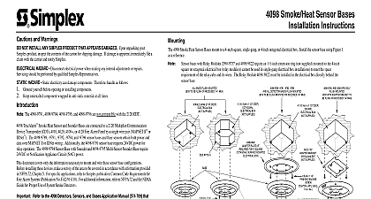
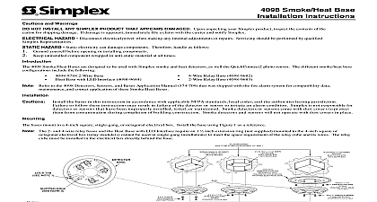
4098 9793 Isolator Sensor Base Instructions 4098 TrueAlarm cid 226 4098 9793 sensor bases and their sensors obtain both power and data over IDNet wiring Isolator Sensor Base connects to a 4010 Fire Alarm Control Panel by a single wire pair IDNet cid 212 document covers only the information necessary to mount and wire this sensor base configuration Before installing device make a survey of the area to be covered in accordance with information provided in NFPA 72 Chapter 5 For applications refer to Simplex publication Common Code Requirements for Fire Alarm Systems Publication No For additional information refer to NFPA 72 and the NEMA Guide for Proper Use of System Smoke to the 4098 Detectors Sensors and Bases Application Manual 574 709 that was shipped with the fire system for compatibility and specification data address settings maintenance and correct application of Sensor Bases the base described in this instruction in accordance with applicable NFPA standards local and the authorities having jurisdiction Failure to follow these instructions may result in of the sensor to initiate an alarm condition Simplex is not responsible for sensors that have improperly installed tested or maintained smoke sensors come with dust covers to protect them from contamination during completion building construction Sensors will not operate with dust covers in place 4098 9793 Isolator sensor base mounts to a 4 inch square single gang or 4 inch octagonal electrical box Install the base using Figure 1 as a reference 2 illustrates the wiring connections for the isolator sensor base All screw terminals accept 14 to 18 gauge AWG or stranded wire Maximum torque should not exceed 12 inch pounds Connect wiring to terminals as illustrated Figure 2 following an 8 digit Product ID number denotes ULC listed product following an eight digit Product ID number denotes Global product The 2nd identifies market country models with this suffix are not UL Listed is protected by U S Patent No 5,155,468 is a trademark of Simplex Time Recorder Company 1999 Simplex Time Recorder Co Gardner MA 01441 0001 USA 1999 Simplex International Time Equipment Co Ltd Mississauga Ontario L4V 1H3 Canada specifications and other information shown were current as of publication and are subject to change without notice C MOUNTED TO BE FLUSH OR RECESSED 1 4 MAX GANG 2 1 8 DEEP BOX SUPPLIED 10.16cm x 1 1 2 DEEP BOX NOT SUPPLIED 10.16cm x 1 1 2 DEEP BOX SUPPLIED PLATE KIT FOR 4 OR ANY SURFACE ELECTRICAL BOX SWITCHES NOTE 2 HOLE NOTE 3 TAB NOTE 1 6 32 SCREW WASHER SUPPLIED 8 32 x 1 1 4 MACHINE TO 4 6 in lbs REQUIRED NOTES 1 AND 2 ATTACHMENT 8 32 x 1 1 2 MACHINE UNTIL SNUG in lbs 8 x 1 THREAD FORMING SCREW TO 4 6 in lbs Base Break off plastic lock tab to engage locking mechanism To sensor into base turn unit until the locking tab clicks into To unlock sensor insert the blade of a screwdriver into slot and then pull down on handle This action allows the to be turned and removed Refer to the 4098 Detectors Sensors and Bases Application 574 709 for detailed information on compatible and DIP Switch Address Settings Use the slotted hole indicated for the first screw when the sensor base 1 Base Mounting OTHER DEVICES NOTE 2 IS OPTIONAL SEE NOTE 3 Base compatible with 4010 panel only Maximum quantity of devices per circuit is 250 for 4010 panel shield is used twist shield wires together with wire nut Shield should be insulated from electrical box 2 Isolator Sensor Base Connections C