Simplex CDT Expansion Power Supply – Interconnection Diagrams

File Preview
Click below to download for free
Click below to download for free
File Data
| Name | simplex-cdt-expansion-power-supply-interconnection-diagrams-1982043567.pdf |
|---|---|
| Type | |
| Size | 1.04 MB |
| Downloads |
Text Preview
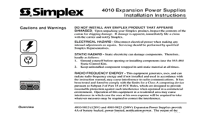
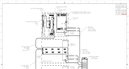
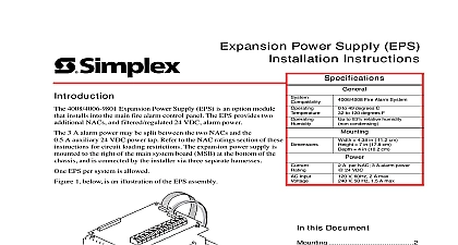
4100 5153 4100 5154 XPS Diagrams publication provides interconnection diagrams for 4100 5153 120 VAC and 4100 5154 VAC 13 A Expansion Power Supplies XPS Contents Shipment unpacking your Simplex product inspect the contents of the carton for shipping damage If is apparent immediately file a claim with the carrier and notify Simplex this Publication publication discusses the following topics and Warnings Diagrams Page 2001 2011 SimplexGrinnell LP All rights reserved and other information shown were current as of publication and are subject to change without notice and the Simplex logo are trademarks of Tyco International Ltd and its affiliates and are used under license B and Warnings and AND SAVE THESE INSTRUCTIONS Follow the instructions in this installation These instructions must be followed to avoid damage to this product and associated Product operation and reliability depend upon proper installation NOT INSTALL ANY SIMPLEX PRODUCT THAT APPEARS DAMAGED Upon your Simplex product inspect the contents of the carton for shipping damage If is apparent immediately file a claim with the carrier and notify an authorized product supplier HAZARD Disconnect electrical field power when making any internal adjust or repairs All repairs should be performed by a representative or authorized agent of local Simplex product supplier HAZARD Static electricity can damage components Handle as follows yourself before opening or installing components to installation keep components wrapped in anti static material at all times SAFETY HAZARD Under certain fiber optic application conditions the optical output this device may exceed eye safety limits Do not use magnification such as a microscope other focusing equipment when viewing the output of this device RULES AND REGULATIONS PART 15 This equipment has been tested and found to with the limits for a Class A digital device pursuant to Part 15 of the FCC Rules limits are designed to provide reasonable protection against harmful interference when equipment is operated in a commercial environment This equipment generates uses and radiate radio frequency energy and if not installed and used in accordance with the manual may cause harmful interference to radio communications Operation of equipment in a residential area is likely to cause harmful interference in which case the will be required to correct the interference at his own expense REACCEPTANCE TEST AFTER SOFTWARE CHANGES To ensure proper system this product must be tested in accordance with NFPA 72 after any programming or change in site specific software Reacceptance testing is required after any addition or deletion of system components or after any modification repair or to system hardware or wiring components circuits system operations or software functions known to be affected by a must be 100 tested In addition to ensure that other operations are not affected at least 10 of initiating devices that are not directly affected by the up to a maximum of 50 devices must also be tested and proper system operation 72 is a registered trademark of the National Fire Protection Association and 4100 5154 13 A Expansion Power Supplies Description Amp Power Supply VDC maximum at 132 264 VAC input 4100 5153 120 VAC and 4100 5154 220 240 VAC 13 amp Expansion Supplies XPS deliver 28 VDC at 5 amps and signal power at 8 amps power is de rated to 5 amps when signal power is used to power ZAMs Power 2 3 Signal 5 6 Signal load Load 5 amp load 20.4V at 102 204 VAC input amp load 19.0V at 102 204 VAC input 2V Peak to Peak at 120Hz at full load Protection signal power option has short circuit protection via a 15 amp fuse which is on the power supply assembly signal power output is monitored for an open circuit blown fuse or in which case a TTL level output 10W level on P4 2 will indicate a to the CDT and 4100 5154 Interconnection Diagrams 1 Connecting Internal Batteries on next page and 4100 5154 Interconnection Diagrams Continued 2 Connecting Internal Batteries with Battery Monitor on next page and 4100 5154 Interconnection Diagrams Continued Remove Terminal Block from Harness Assembly 733 414 3 Connecting External Batteries on next page and 4100 5154 Interconnection Diagrams Continued Remove Terminal Block from Harness Assembly 733 414 4 Connecting External Batteries with Battery Monitor on next page and 4100 5154 Interconnection Diagrams Continued 5 Power Supply with 2120 RS232 to DC Communications Connections on next page and 4100 5154 Interconnection Diagrams Continued 6 Power Supply with ZAM and 2120 DC COMM To RS232 Connections on next page and 4100 5154 Interconnection Diagrams Continued Cut and strip unshielded harness as required 9008 997 may be used in place of ground wire on 562 346 depending on required See Figures 1 through 4 for battery 7 Power Supply with 2120 COMM Repeater on next page and 4100 5154 Interconnection Diagrams Continued Cut and strip unshielded harness as required See Figures 1 through 4 for battery connections 8 Power Supply with 2120 DC COMM To RS232 on next page and 4100 5154 Interconnection Diagrams Continued Cut and strip unshielded harness to length See Figures 1 through 4 for battery connections 9 Power Supply with Fiber Optic Board Interconnect Single Unit Style 4 on next page and 4100 5154 Interconnection Diagrams Continued Cut and strip unshielded harness to length See Figures 1 through 4 for battery connections 10 Power Supply with Fiber Optic Style 7 BMUX to U T to Fold Interconnect on next page and 4100 5154 Interconnection Diagrams