Solidyne M2 Data Sheet

File Preview
Click below to download for free
Click below to download for free
File Data
| Name | solidyne-m2-data-sheet-8264193570.pdf |
|---|---|
| Type | |
| Size | 826.74 KB |
| Downloads |
Text Preview
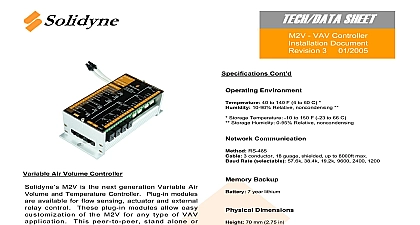
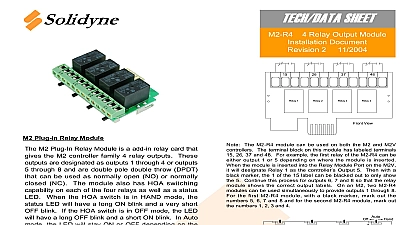
M2 Universal Controller Document 1 01 2005 Cont Environment 40 to 140 F 4 to 60 C 10 90 Relative noncondensing Storage Temperature 10 to 150 F 23 to 66 C Storage Humidity 0 95 Relative noncondensing Communication RS 485 3 conductor 18 guage shielded up to 8000ft max Rate selectable 57.6k 38.4k 19.2k 9600 2400 1200 Backup 7 year lithium Dimensions 70 mm 2.75 in 78 mm 3.0 in 160 mm 6.3 in Holes 148.5 mm 5.85 in Center to Center 1.2 lb Approvals Device Pending is in the process of UL CSA approval for the entire M2 family and associated modules Please use Solidyne UL number E76576 24G9 for all references to agency approvals Stand Alone Controller M2 is the next generation Universal Controller including real time clock and day calendar Offering 100 compatibility with controllers ICMS software and i3 networks the M2 a seamless upgrade path for existing projects 8 universal inputs and 8 analog outputs built in M2 can be expanded to include 4 or 8 digital using plug in modules This modular provides customization of the M2 for any of application Requirements Voltage 23 to 28 VAC 50 60 Hz 1.7 VA without optional plug in modules 10.3 VA all optional plug in modules used Voltage Fuse Resetable fuse rated at 1.1A at 24VAC Inputs 8 Analog Inputs be independently configured for thermistor digital or 4 20mA Thermistor Inputs are 3k 10k 100kohm thermistor Type 3 Outputs 8 0 10vdc Analog Outputs Can drive down to 10Kohm loads at 10vdc Outputs to Eight 8 Digital Outputs Eight 8 digital outputs would require two 2 plug in relay modules REV 1 01 2005 Solidyne Corporation 4215 Kirchoff Rd Rolling Meadows IL 60008 800 648 3980 www solidyne com MODULE M2 R4 MODULE M2 R4 ON FIG 1 FOR SELECTIONS COM COM COM COM HOT NEUTRAL RS 485 LAN COMM CONNECTION RS 485 LAN COMM CONNECTION RS 485 LAN COMM CONNECTION INPUT 1 INPUT 2 INPUT 3 INPUT 4 INPUT 5 INPUT 6 INPUT 7 INPUT 8 OUTPUT TRANSDUCER POWER 25mA MAX OUTPUT 1 OUTPUT 2 OUTPUT 3 OUTPUT 4 OUTPUT 5 OR IO COMMON JUMPER SELECTABLE OUTPUT 6 OR IO COMMON JUMPER SELECTABLE OUTPUT 7 OR IO COMMON JUMPER SELECTABLE OUTPUT 8 OR IO COMMON JUMPER SELECTABLE AND OUTPUT COMMON Installation Notes sure that BATT JUMPER is place before powering unit with on board POWER unit is powered ON LED flash 1 second on 1 off continuously when is operating This flashing as a heartbeat and that the unit on It will not flash or when unit is off inserting or removing modules or display such as DU 1 M2 must powered OFF or damage will is internally protected over current by a 1.1 self resetting fuse will protect the 24VAC powering the M2 being damaged due to the failing internally 8v output is used for low power Solidyne 1 INPUT JUMPERS NOTE 2 INPUT LED NOTE 3 OUTPUT OR COMMON SELECTION NOTE 1 1 JUMPERS DEFINE THAT TERMINALS 20 23 USED AS ANALOG OUTPUT OR ADDITIONAL INPUT OUTPUT COMMON EX AO8 JUMPER SET TO AO JUMPER SET TO COMMON 2 JUMPERS DEFINE THAT INPUT IS DIGITAL 0 10V OR THERMISTOR EX INPUT 4 SET TO 0 10VDC INPUT 6 JUMPER SET TO INPUT 8 JUMPER SET TO DIGITAL JUMPER NEEDED TO DEFINE INPUT AS 3 DIGITAL INPUT LED WILL ONLY WHEN INPUT IS SHORTED TO COM FUTURE USE FUTURE USE 7 6 5 4 3 2 1 Selection MUST HAVE 8 PIN RJ 45 M2 SIDE TERMINAL DU 1 TO PROPERLY CONNECT ALSO HAVE BEEN PURCHASED NOV 2004 HAS INTERNAL TEMPERATURE THAT WILL USE INPUT 1 IF THERE IS NO DEVICE TO INPUT 1 IF INPUT 1 IS USED FOR ANOTHER DU 1 WILL OPERATE AND ITS INTERNAL SENSOR WILL BE LED T RECEIVE LED R POWER ON HEARTBEAT LED ON SWITCH


