System Sensor 1012B

File Preview
Click below to download for free
Click below to download for free
File Data
| Name | system-sensor-1012b-7803941265.pdf |
|---|---|
| Type | |
| Size | 720.20 KB |
| Downloads |
Text Preview
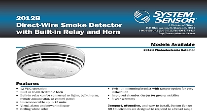
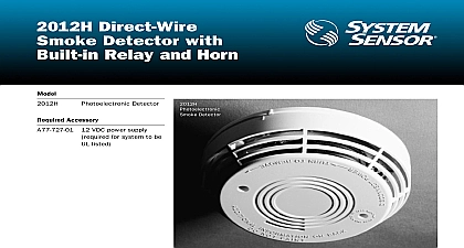
1012B 2012B Smoke Detector Built in Relay and Horn Division of Pittway Ohio Avenue St Charles IL 60174 736 7672 Fax 630 377 6495 Available Ionization Detector Photoelectronic Detector 12 VDC operation 4 wire Built in 85dB electronic horn Built in relay can be connected to lights bells horns annunciator or control panel Interconnectable up to 12 units Visual alarm and power indicator Ceiling white color Built in 8 second delay on relay output Built in test switch Twist on mounting bracket with tamper option for easy Improved chamber design for greater stability Same housing design for both ion and photo models 3 year warranty attractive and easy to install System Sensor and 2012B detectors are designed to respond to a range of fires while providing maximum stability units in this series feature low voltage wiring you to choose the detector that best suits your h 5.5 dia mm h 140 mm dia oz 150 grams to 93 RH noncondensing Detector Spacing smooth ceilings as defined in NFPA 72 spacing of feet 900 sq ft may be used as a guideline Other may be used depending on ceiling height high movements and other conditions or response Range Ratings Voltage Contact Rating Current Current Range VDC nominal Form A 5 A 30 VDC m A maximum average mA maximum average 12 VDC to 120 cid 176 F 0 cid 176 to 50 cid 176 C System Sensor 8 96 document is not intended to be used for installation purposes Description Sensor 1012B ionization and 2012B photoelectronic are designed primarily for applications where Class 2 wiring may be used These detectors self resetting and offer an 85dB alarm horn An push button provides a test of the detectors function Up to 12 units can be interconnected so if one detector alarms all detectors alarm A normally auxiliary alarm relay is available for controlling functions A visible LED indicator flashes once 40 seconds in standby and rapidly in alarm when smoke The detectors offer low voltage operation a tamper proof feature Screw terminals and a bracket are provided for easy installation RED A77 727 O1 cid 13 BLACK POWER cid 13 12OVAC GRAY BLACK UP TO cid 13 DETECTORS INPUT INPUT INPUT INPUT INPUT INPUT ALARM RELAY INTERCONNECT UP TO 12 DETECTORS UNITS cid 13 UNITS cid 13 POWER BUS LENGTH IN FEET GIVEN NUMBER OF cid 13 MAXIMUM PER BUS AND WIRE SIZE UNIT cid 13 UNITS cid 13 UNITS cid 13 INTERCONNECT BUS LENGTH cid 13 FT NO 18AWG OR LARGER DUAL CONDUCTOR CABLE cid 13 WIRING MUST CONFORM TO LOCAL ELECTRICAL CODES cid 13 CONTACTS RATING 0.5A 30VDC 0.5A 30VAC cid 13 UNITS cid 13 UNITS cid 13 UNITS cid 13 UNITS cid 13 UNITS cid 13 UNITS cid 13 UNITS cid 13 Wiring Diagram Information No smoke detector with relay 12 VDC station smoke detector with relay 12 VDC station 12 VDC power supply mounts to a 4 square box deep Sensor Worldwide Distribution India Canada Sensor India Sensor Canada Maheshwari Nagar Kitimat Road Unit 7 Mills Lane Ontario East Mumbai 400093 L5N 3T5 91 022 8202564 905 812 0767 905 812 0771 the United Kingdom Sensor Europe Ltd Gates III North St West Sussex 5PJ United Kingdom 44 1403 276500 44 1403 276501 2 the Far East Sensor Far East Ltd 706 New T T Centre Canton Road Kowloon Hong Kong 852 2730 9090 852 2736 6580