System Sensor 1400 1412B 1424

File Preview
Click below to download for free
Click below to download for free
File Data
| Name | system-sensor-1400-1412b-1424-6138702495.pdf |
|---|---|
| Type | |
| Size | 692.38 KB |
| Downloads |
Text Preview
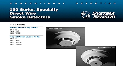
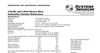
C o n v e n t i o n a l e t e C t i o n Series Ionization Detector 2 Wire Ionization Smoke Detector Available 2 Wire 4 Wire 4 Wire VDC LED annunciator End of line relay module Sensitivity test module cover removal tool screen Overview or 24 volt operation cover and insect screen for cleaning LED blinks in standby latches on alarm mounting bracket with option unipolar chamber design 400 Series ionization smoke detectors include a unique dual source dual unipolar detection design which will sense the presence of smoke particles produced by combustion as well as slow smoldering fires This chamber exhibits increased stability reduces nuisance alarms and provides better performance at higher air 400 Series meets the performance criteria required by UL ULC Additional key include an LED which blinks in standby and latches on to indicate an alarm feature convenient field testing and sensitivity metering The model 1400 remote LED annunciator capabilities using the RA400Z sensitivity metering of detector to NFPA 72 requirements Specifications screws for easy wiring warranty against dirt insects and pressure detector shall be an ionization type model 1400 1412B or 1424 as manufactured System Sensor Wiring connections shall be made by means of SEMS screws Detector have a visible LED which will blink in standby and latch on in alarm The detector have a sensitivity of 1.9 0.6 ft as measured in the UL smoke box The detector and cover should be easily removable for cleaning It shall be possible to perform a and functional test on the detector without the need of generating smoke The shall have a mounting bracket that allows for mounting to a 31 2 or 4 octagon or 4 square electrical box II 8.1 cm 13.9 cm Weight lbs Temperature Range to 120 0 to 49 Humidity Range to 93 Relative non condensing Velocity Rating fpm maximum 0.6 ft nominal AWG twisted pair recommended 1 2 or 4 octagon box square box with plaster ring 60 75 mm boxes per NFPA 72 and local require On smooth flat ceilings spac of 30 feet may be used as a guide Ratings Operating Voltage Current VDC 8.5 35 VDC max control panels be current limited mA or less VDC 11.3 17.3 VDC max mA VDC 20 29 VDC max mA Contact Ratings Form A Alarm Form C Auxiliary Alarm 30 VAC DC 30 VAC DC 6A 110 VDC 1A 125 VAC Information Number detector 2 wire 12 24 VDC for control panels detector 4 wire 12 VDC for control panels detector 4 wire 24 VDC for control panels of line relay module 12 24 VDC annunciator LED Test module see below cover removal tool screen MOD400R Field Sensitivity Test Module be used with any standard DC voltmeter multimeter to check the sensitivity range System Sensor detectors satisfies NFPA requirement for sensitivity testing Sensor Sales and Service Sensor Headquarters Ohio Avenue Charles IL 60174 800 SENSOR2 630 377 6495 Sensor Canada 905.812.0767 905.812.0771 Sensor Europe 44.1403.276500 44.1403.276501 Sensor in China 86.29.8832.0119 86.29.8832.5110 Sensor in Singapore 65.273.2230 65.273.2610 Sensor in Far East 85.22.191.9003 85.22.736.6580 Sensor in Australia 613.54.281.142 613.54.281.172 Sensor India 91.124.637.1770 x 2700 91.124.637.3118 Sensor Russia 70.95.937.7982 70.95.937.7983 2003 System Sensor The company reserves the right to change product specifications without notice