System Sensor 2412AT, 2424AT and 2424AIT Manual

File Preview
Click below to download for free
Click below to download for free
File Data
| Name | system-sensor-2412at-2424at-and-2424ait-manual-8276509134.pdf |
|---|---|
| Type | |
| Size | 758.64 KB |
| Downloads |
Text Preview
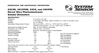
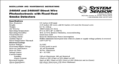
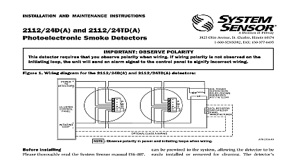
INSTALLATION AND MAINTENANCE INSTRUCTIONS 2424AT and 2424AIT Wire Photoelectronic with Heat Smoke Detectors Division of Pittway 3825 Ohio Avenue St Charles Illinois 60174 FAX 630 377 6495 with Thermal Temperature Humidity Indicator Alarm Signal Ratings Voltage Supply Time Characteristics inches 14 cm inches 8.1 cm lb 310 g to 38 cid 176 C 32 cid 176 to 100 cid 176 F to 95 Relative Humidity Non condensing State LED by momentary power interruption minimum interrupted tone when individual unit is in alarm or when the voltage is reversed or 2424AIT Unfiltered Unfiltered 7mA Maximum with RA400Z Remote Annunciator LED m A Max m A Max seconds maximum Form A SPST NO for alarm initiation 1.25A at 30 VAC DC Installing thoroughly read the System Sensor manual I56 407 Guide for Proper Use of System Smoke Detectors which detailed on detector spacing zoning wiring and special applications Copies this manual are available at no charge from System For installations in Canada refer to CAN Standard for the Installation of Fire Alarm Systems CEC Part 1 Sec 32 Description smoke detectors are designed to provide area protection and to be used with UL listed 4 wire panels The 2412AT operates at 12 VDC and the and 2424AIT operate at 24 VDC The sensor in this operates on the light scattering principle and a unique photo optic sensing chamber that good smoke entry while minimizing the effects of light These detectors also provide restorable F fixed temperature heat detection The 2412AT and heat detection unit sensor while the 2424AIT heat detection is isolated from the photoelectronic smoke sensor and be monitored separately In addition a piezoelectric in each detector produces an interrupted 85 dBA with tone when the individual detector alarms or the supply voltage polarity is reversed LED on each detector lights to provide a local alarm and will remain on when the supply polarity is A screw terminal is provided for a remote LED optional accessory RA400Z These detectors listed to UL268 and are latching type system detectors alarm can be reset only by momentary power For testing these detectors have a test switch may be tested by inserting a calibrated test card in a test after removing the detector cover detector contains one Form A SPST NO contact for to an alarm initiating circuit Supervision of the power is accomplished by installing a Power End of Line Relay Module A77 716 at the end the detector power loop When power is applied to and the detectors the EOL Power Supervisory Module energized Its relay contacts close and provide a closed circuit in the control panel alarm initiating loop A failure or break in the detector power loop de the EOL Module The relay contacts open and a trouble signal at the control panel 1 Flush mounting of detector on 4 inch box 2 Detector mounting bracket MAKE DETECTOR TAMPER RESISTANT OFF TAB EXTENSION SCRIBED LINE Instructions 2400 Series detector unit is supplied with a mounting kit that permits several mounting techniques Units may be mounted directly to a 3 inch or 4 inch octagonal inch deep electrical box See Figures 1 and 2 Units may be mounted to a 4 inch square electrical box by plaster ring with the supplied mounting bracket kit Feature detector includes a tamper proof feature that when prevents removal of the detector without the use a tool To activate this feature cut off smaller tab at the line on tamper proof tab located on the detector bracket see Figure 2 Install the detector To the detector from the bracket once the tamper feature has been activated depress the tamper proof located in the slot on the mounting bracket and turn the counterclockwise for removal and all smoke alarms before the panel gives the battery low signal When the battery low signal is the battery should be capable of providing power for 7 days after which the backup battery should have energy left to allow a 4 minute alarm signal to be by all connected smoke alarms Installation Guidelines wiring must be in compliance with the National Code and the applicable local codes and any requirements of authority having Proper wire gauges should be used The used to connect smoke detectors to control and accessory devices should be color coded to wiring mistakes Improper connections can prevent system from responding properly in the event of a fire signal wiring the wiring between interconnected wire no smaller than 18 AWG is recommended sizes up to 12 AWG may be used For best system the power and loop wires should be pair and installed in separate grounded conduit or cable to protect the loop from extraneous electrical If a cable shield is provided the shield con to and from the detector must be continuous by wire nuts crimping or soldering as appropriate for a connection connections are made by stripping about 3 8 of from the end of the wire use strip gauge molded base sliding the bare end of the wire under the plate and tightening the clamping plate screw not loop the wire under the clamping plate detectors In Australia Only installation temperature range for Australia is 5 cid 176 to C and has been tested per the Australian Standard installation temperatures specified for all other when Australia should be installed by qualified technicians of a mains connected power supply unit must performed by qualified electricians only The primary will be provided by a panel type system A recharge battery is required as a backup to the external power in case of a mains failure In standby operation the battery fully charged must be capable of uninterrupted power for at least 7 days to the 3 Class A or Class B wiring diagram for model 2412AT and 2424AT detectors used with four wire panels 4 Additional wiring needed for the isolated thermal unit of the 2424AIT detector thermal units are to a separate loop LISTED cid 13 OR FOUR cid 13 PANEL covers are an effective way to limit the entry of dust smoke detector sensing chambers However they may completely prevent airborne dust particles from the detector Therefore System Sensor recom removal of detectors before beginning or other dust producing activity Be sure to dust covers from any sensors that were left in place construction as part of returning the system to Before testing notify the proper authorities that smoke detector system is undergoing mainte and therefore will temporarily be out of Disable the zone or system undergoing to prevent unwanted alarms must be tested after installation and periodic The 2412AT 2424AT or 2424AIT may be in the following ways Before testing the detector check for the presence the flashing LED If it does not flash power has lost to the detector check the wiring or it is Warranty Recessed Test Switch Push and hold the recessed test switch with a 1 inch diameter tool The LED should latch within 5 seconds indicating and annunciating the panel The horn should sound Calibrated Test Card System Sensor No R59 18 00 Remove the detector cover by placing a small bladed in the side slot of the detector cover it slightly until the cover can be turned for removal Insert the NO ALARM end of the test card fully into Figure 6 sli