System Sensor 2451 with B404BT and RTC

File Preview
Click below to download for free
Click below to download for free
File Data
| Name | system-sensor-2451-with-b404bt-and-rtc-2957164830.pdf |
|---|---|
| Type | |
| Size | 886.90 KB |
| Downloads |
Text Preview
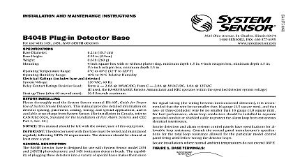
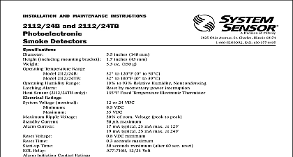
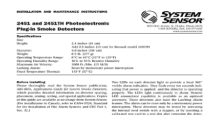
H V A C S Y S T E M S M O N I T O R I N G Smoke for Special with B404B B404BT RTC Remote Test Kit 268A RTC Overview standby current LEDs in standby head plugs easily into base adjustable sensitivity test switch with B404BT and RTC the RTS451 sensitivity metering of detector to meet requirements of NFPA 72 and 24VAC DC bases with built in spring tamper resistant feature for mounting on standard electrical box screws for easy wiring and positive wire cover and insect screen for field System Sensor 2451 photoelectronic smoke detector is UL listed UL 268A specifically for use in no flow low flow air handling sys It designed for installations where a standard Venturi principle smoke detector is unsuitable This is the perfect combination for in ducts where the air velocity is below 500 fpm or for duct as small as 8 inches in diameter Pendant mounted in a standard box within the duct the twist in twist out head allows easy from the base for quick cleaning and maintenance The detec can be combined with the System Sensor B404B 120VAC base or B404BT 24VAC DC base Remote testing is accomplished using our Test Coil accessory that includes the RTS451 The APA451 Annunciator with Piezo Alarm can also be connected to pro an audible and visible indication of smoke detector status Voltage Alarm current base dependent see chart current mA maximum 7 ft ib 277 g cm height cm diameter retardant Noryl plastic Temperature to 120 0 to 49 Range to 93 RH non condensing Velocity Rating to 3000 fpm maximum Specifications air duct detector shall be a System Sensor model 2451 Series Smoke detector UL listed to UL 268A specifically for use in handling systems when used in conjunction with the B404B 120VAC or the B404BT 24VAC DC base The detector shall at air velocities up to 3000 feet per minute It shall be capable of local testing via magnetic switch or remote testing the UL listed RTC Remote Test Coil accessory with the RTS451 Remote Test Station It shall be capable of providing smoke detector status via the UL listed model APA451 Piezo Annunciator Chart Box Selection Type Contact Type Voltage Limit A C A supy A C A supy rms Current Model Gang Oct Oct Sq 60mm 75mm Guide Typical Wiring Diagrams VAC LEADS VAC INITIATION LOOP PANEL Base Terminals Annunciator Used Used Used Annunciator Relay A Contacts Relay A Contacts Relay C Contacts LEADS VAC PANEL INITIATION LOOP Typical Wiring Diagrams VACrms DC INITIATION LOOP VACrms DC ABOVE DIAGRAM SHOWS NFPA REQUIRED WIRING OF SUPERVISED SCHEMATIC SHOWN BELOW FOR REFERENCE PANEL Base Terminals Annunciator Coil Used Annunciator PANEL Relay A Contacts Relay A Contacts Relay C Contacts POWER SOURCE APPROPRIATE TERMINALS EACH DETECTOR SEE FOR POWER SUPPLY VACrms DC WIRING OF AUXILIARY REFER TO INSTRUCTIONS CONTACT MANUFACTURER THE SUPERVISORY RELAY NOW A FORM C CONTACT FOR APPLICATIONS STANDARD APPLICATIONS ONLY NO CONTACT IS USED DAMPER Ring Replacement of B404BT Wiring Diagram COIL RESISTOR BY MANUFACTURER Test Station with Remote Coil Annunciator Annunciator Mount in Ventilation Shaft Information No Description Photoelectronic plug in detector order one of the bases listed below and the RTC 120VAC detector base 24VAC DC detector base Description Remote test coil kit Includes RTS451 remote test station Remote annunciator with piezo alarm Remote annunciator Sensor Sales and Service Sensor Headquarters Ohio Avenue Charles IL 60174 800 SENSOR2 630 377 6495 x3 Sensor Canada 905.812.0767 905.812.0771 Sensor Europe 44.1403.891920 44.1403.891921 Sensor in China 86.29.524.6253 86.29.524.6259 Sensor in Singapore 65.273.2230 65.273.2610 Sensor Far East 85.22.191.9003 85.22.736.6580 Sensor Australia 613.54.281.142 613.54.281.172 Sensor India 91.124.2371770 x 2700 91.124.237.3118 2004 System Sensor The company reserves the right to change product specifications without notice A05 0952 001