System Sensor 400 Series Ionization Smoke Detectors

File Preview
Click below to download for free
Click below to download for free
File Data
| Name | system-sensor-400-series-ionization-smoke-detectors-2543716098.pdf |
|---|---|
| Type | |
| Size | 1.12 MB |
| Downloads |
Text Preview
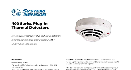
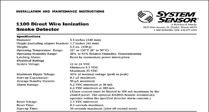
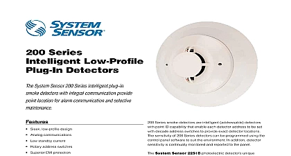
INSTALLATION AND MAINTENANCE INSTRUCTIONS Direct Wire Ionization Detector SENSOR Division of Pittway 3825 Ohio Avenue St Charles Illinois 60174 FAX 630 377 6495 Temperature Alarm Humidity Ratings Voltage Ripple Voltage Capacitance Ratings Ratings Voltage Time Time inches 140 mm inches 80 mm lb 310 g to 49oC 32oF to 120oF by momentary power interruption to 93 Relative Humidity Noncondensing VDC Volts peak to peak uA Maximum VDC Minimum VDC Maximum uA Maximum VDC Minimum at 10 mA VDC Minimum at 100 mA current must be limited to 100 mA maximum by the control panel If used the Remote Annunciator operates within the specified detector alarm currents VDC Minimum S Maximum S Maximum Installing thoroughly read the System Sensor manual I56 407 Guide for Proper Use of System Smoke Detectors This provides detailed information on detector spacing zoning wiring and special applications Copies this manual are available at no charge from System Sen For installation in Canada refer to CAN ULC S524 for the Installation of Fire Alarm Systems and CEC 1 Sec 32 Description Sensor 1400 dual chamber ionization smoke detec utilize state of the art unipolar sensing chambers detectors are designed to provide open area protec and to be used with compatible UL listed 2 wire con panels only The detector operation and sensitivity be tested in place detector includes an LED that provides a local visual of the detector status The LED blinks every ten as an indication that power is applied to the detec and lights continuously in alarm These detectors also the latching alarm feature The alarm can be reset by a momentary power interruption detector also has provision for the connection of an Model RA400Z Remote Annunciator The RA400Z a visual indication of an alarm and mounts to a gang box 72 defines the spacing requirements for smoke detec Typically this is 30 feet when the detectors are in on a smooth ceiling However ALL installations comply with NFPA 72 and or special requirements of authority having jurisdiction Manuals Online 1 Surface mounting of Model 1400 detector 3 1 2 and 4 inch octagonal box 2 Model 1400 detector mounting bracket MAKE DETECTOR TAMPER RESISTANT OFF TAB EXTENSION SCRIBED LINE 1400 detector is supplied with a mounting bracket kit permits the detector to be mounted Directly to a 3 1 2 inch or 4 inch octagonal 1 1 2 inch electrical box or To a 4 inch square electrical box by using a plaster ring the supplied mounting bracket kit Wiring Guidelines wiring must be installed in compliance with the Na Electrical Code and all applicable local codes and special requirements of the authority having jurisdic using the proper wire size The conductors used to smoke detectors to control panels and accessory should be color coded to reduce the likelihood of errors Improper connections can prevent a system responding properly in the event of a fire signal wiring the wiring between interconnected de it is recommended that the wire be no smaller AWG 18 However the screws and clamping plate can wire sizes up to AWG 12 The use of twisted wiring for the power and loop is recommended minimize the effects of electrical interference Manuals Online detectors and alarm system control panels have for allowable loop resistance Consult the panel manufacturer specifications for the total resistance allowed for the control panel being used be wiring the detector loops electrical connections by stripping about 3 8 insula from the end of the wire Then slide the bare end of wire under the clamping plate and tighten the clamping screw A wiring diagram for a typical 2 wire detector is shown in Figure 3 Break the wire at each terminal to ensure that the are supervised Do NOT loop the wire the terminals Sensor smoke detectors are marked with a compat identifier located as the last digit of a five digit code on the back of the product Connect detectors only compatible control units as indicated in System Sensor chart which contains a current list of UL control units and detectors A copy of this list is avail from System Sensor upon request Feature detector includes a tamper resistant feature that effec prevents removal of the detector without the use of a To make the detector tamper resistant break off the tab at the scribed line on the tamper resistant tab the detector mounting bracket see Figure 2 then in the detector To remove the detector from the bracket it has been made tamper resistant use a small screw to depress the tamper resistant tab located in the slot the mounting bracket and turn the detector counter for removal the power to the alarm system control unit be installing detectors Wire the detector following the installation guidelines Line up arrows on the detector with the arrows on the Rotate the detector clockwise until it clicks into place After all detectors have been installed apply power to bracket control unit Test the detector as described under TESTING Reset the detector at the system control panel Notify the proper authorities that the system is in opera 3 Wiring diagram for 1400 smoke detector used with two wire control panel LISTED IF REMOTE ANNUNCIATOR IS NOT USED POLARITY TO DETECTOR MAY BE REVERSED A OPTIONAL WIRING covers can be used to help limit dust entry to the de but they are not a substitute for removing the detec during building construction Remove any dust covers placing system in service testing the detector look for the presence of the LED If it does not flash power has been lost to the check the wiring or it is defective return for re refer to Warranty must be tested after installation and following maintenance Notify the proper authorities that system is undergoing testing The 1400 may be tested follows Recessed Test Switch A test switch is located on the detector housing See 4 Push and hold the recessed test switch with a 0.1 inch diameter tool The LED on the detector should light within 5 Test Module System Sensor Model No MOD400R MOD400R is used with an analog or digital voltme to check the detector sensitivity as described in the module manual Aerosol Generator Gemini 501 the generator to represent 4 Ft to 5 Ft obscura as described in the Gemini 501 manual Using the shaped applicator apply aerosol until the unit the proper authorities that the system is back on that fail these tests should be cleaned as de under MAINTENANCE and retested If the detec still fail these tests they should be returned for repair 4 Bottom and side views showing position of test switch SWITCH SLOT MODULE RECESSED TEST SWITCH WITH 0.1 MAX DIAMETER TOOL Manuals Online 5 Removal of cover and screen for cleaning OF LOCKING ON FOR SCREEN RS14 PRONG Before starting notify the proper authorities that smoke detector system is undergoing mainte and therefore will be temporarily out of Disable the zone or system undergoing to prevent unwanted alarms 1400 is cleaned as follows Remove the detector screen and cover assembly by de the three lock prongs on the top of the cover ro the cover clockwise and pulling the screen cover away from the detector see Figure 5 Use of System Sensor CRT400 cover removal tool is recom Remove the screen from the cover Use a vacuum cleaner to remove dust from the screen cover and the