System Sensor 546-9000 Cover Tamper Swtch Manual

File Preview
Click below to download for free
Click below to download for free
File Data
| Name | system-sensor-546-9000-cover-tamper-swtch-manual-1572649803.pdf |
|---|---|
| Type | |
| Size | 623.87 KB |
| Downloads |
Text Preview
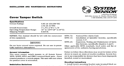
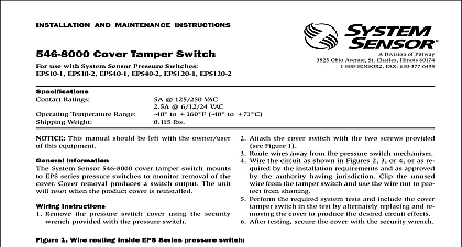
INSTALLATION AND MAINTENANCE INSTRUCTIONS Cover Tamper Switch use with System Sensor Models and LFD Series waterflow detectors Division of Pittway 3825 Ohio Avenue St Charles Illinois 60174 FAX 630 377 6495 Ratings Temperature Range Weight 125 250 VAC 30 VDC to 120 F 0 to 49 C lbs This manual should be left with the owner user this equipment Information System Sensor 546 9000 cover tamper switch mounts AFD and LFD Series waterflow devices to monitor re of the cover Cover removal produces a switch out The unit will reset when the product cover is Instructions Remove the waterflow detector cover using the security provided Attach the cover tamper switch to upper PCB by snap The cover tamper switch assembly snaps into the mounting holes on the upper PCB in the orienta shown in Figure 1 1 avoid possible damage support upper PCB installing cover tamper switch bracket as Secure the three wires from cover tamper switch to lower using supplied tie wrap See Figure 1 Route wires away from mechanisms Wire the circuit as shown in Figures 2 3 or 4 or as re by the installation requirements and as approved the authority having jurisdiction Clip the unused from the tamper switch and use the wire nut to pro from shorting Perform the required system tests and include the cover switch in the test by alternately replacing and re the cover to produce the desired circuit effects After testing secure the cover with the security wrench TAMPER SWITCH ASSEMBLY 546 9000 PCB PCB COVER TAMPER SWITCH OPEN CLOSED OFF WRAP COM NORMALLY OPEN NORMALLY CLOSED MOUNTING HOLES 2 Class B initiating circuit with single device OF LINE 3 Class B initiating circuit with multiple devices OF LINE 4 Class A 4 wire initiating circuit with multiple devices ZONE OF LINE Limited Warranty Sensor warrants its enclosed cover tamper switch to be free from in materials and workmanship under normal use and service for a of three years from date of manufacture System Sensor makes no express warranty for this cover tamper switch No agent representa dealer or employee of the Company has the authority to increase or the obligations or limitations of this Warranty The Company obli of this Warranty shall be limited to the repair or replacement of any of the cover tamper switch which is found to be defective in materials workmanship under normal use and service during the three year pe commencing with the date of manufacture After phoning System toll free number 800 SENSOR2 736 7672 for a Return Authori number send defective units postage prepaid to System Sensor Department RA 3825 Ohio Avenue St Charles IL Please include a note describing the malfunction and suspected of failure The Company shall not be obligated to repair or replace which are found to be defective because of damage unreasonable modifications or alterations occurring after the date of manufacture no case shall the Company be liable for any consequential or incidental for breach of this or any other Warranty expressed or implied even if the loss or damage is caused by the Company negli or fault Some states do not allow the exclusion or limitation of inci or consequential damages so the above limitation or exclusion may apply to you This Warranty gives you specific legal rights and you also have other rights which vary from state to state System Sensor