System Sensor DH100ACDCLP
File Preview
Click below to download for free
Click below to download for free
File Data
| Name | system-sensor-dh100acdclp-8706523941.pdf |
|---|---|
| Type | |
| Size | 830.35 KB |
| Downloads |
Text Preview
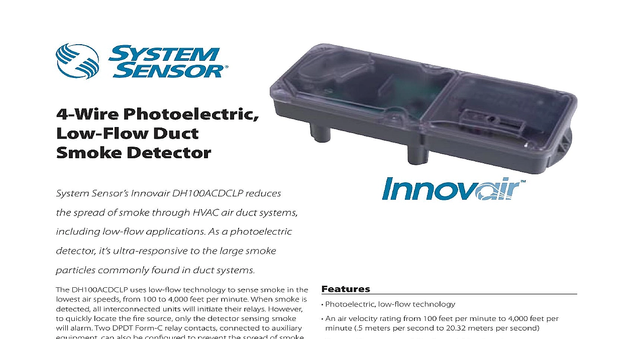
4 Wire Photoelectric Duct Detector Sensor Innovair DH100ACDCLP reduces spread of smoke through HVAC air duct systems low flow applications As a photoelectric it ultra responsive to the large smoke commonly found in duct systems DH100ACDCLP uses low flow technology to sense smoke in the air speeds from 100 to 4,000 feet per minute When smoke is all interconnected units will initiate their relays However quickly locate the fire source only the detector sensing smoke alarm Two DPDT Form C relay contacts connected to auxiliary can also be configured to prevent the spread of smoke a particular area DH100ACDCLP is simple to install and maintain Powered by VAC DC or 120 240 VAC it can be easily mounted to round and ducts from one to twelve feet in width with outside tabs It also offers an adjustable telescopic sampling tube can be used for duct widths up to 18 inches This tube locks into no additional tools are necessary modular construction allows for easy cleaning and field of the power and sensor boards Also simplifying is a transparent cover that provides convenient visual If the cover is removed a patented cover tamper trouble gives a 7 minute delay before the panel or remote accessory is of trouble a remote location the remote test station option ensures that detector is functioning properly and the remote sounder LED option signals if a detector is in alarm However the cover not need to be removed if a detector needs to be reset at the Simply push the built in reset button Duct smoke detectors are NOT a substitute for open smoke detectors NOT a substitute for early warning detection NOT a replacement for a building regular fire detection system to NFPA 72 and 90A for additional information low flow technology air velocity rating from 100 feet per minute to 4,000 feet per 5 meters per second to 20.32 meters per second interconnectability for multi fan shutdown DPDT Form C relay contacts VAC DC or 120 240 VAC mounting options mounting tabs patented telescopic sampling tube construction patented cover tamper trouble signal transparent cover remote test station sounder LED indicator options built in reset button Listings Duct Smoke Detector Specifications Specifications 37 cm Length 5 14 cm Width 2 7 cm Depth lbs 1.7 kg to 131 0 to 55 to 158 to 70 to 93 relative humidity non condensing to 4000 ft min 0.5 to 20.32 m sec air duct smoke detector shall be a System Sensor Model DH100ACDCLP Series Duct Smoke Detector The detector housing shall be UL listed per UL 268A for use in air handling systems The detector shall operate at air velocities of 100 feet per minute to 4000 feet per minute 0.5 to 20.32 m sec The shall be capable of controlling up to ten 10 air handling systems when interconnected with other detectors The detector shall be capable of providing a signal in the event that the front cover is removed It shall be capable of local testing via magnetic switch or remote testing using the SSK451 Multi Accessory or the RTS451KEY Remote Test Station The unit shall be reset by local reset button or remote test station The duct smoke detector housing incorporate an airtight smoke chamber in compliance with UL 268A Standard for Smoke Detectors for Duct Applications The housing shall be capable mounting to either rectangular or round ducts without adapter brackets An integral filter system shall be included to reduce dust and residue effects on and housing thereby reducing maintenance and servicing Sampling tubes shall either be telescoping or be easily installed by passing through the housing after the housing is mounted to the duct The unit shall provide a spacial separation of no less than 1 6.4 mm and or a physical barrier between high and low voltage terminals The enclosure shall meet all applicable NEC and NFPA standards regarding electrical junction boxes Terminal connections be of the strip and clamp method suitable for 12 AWG wiring Specifications Weight Temperature Range Temperature Range Humidity Range Duct Velocity Ratings DH100ACDCLP Includes Detector supply voltage capacitance voltage time with RTS451 time by power down up time response time Test Requirements Using No Accessories standby current alarm current Ratings initiation contacts SPST auxiliary contacts DPDT Alarm auxiliary contacts must switch 100mA minimum at 5VDC Alarm auxiliary contacts shall not be connected to initiating circuits of control panels Use VAC 50 60 Hz 20 VAC min to 0.3 sec 0.6 sec max sec max to 17 sec detector label VDC max VDC min to 0.3 sec sec max sec max to 17 sec detector label VAC 50 60 Hz 270 max 2.0 VAC min to 0.3 sec sec max sec max to 17 sec detector label VAC 50 60 Hz VAC min to 0.3 sec sec max sec max to 17 sec detector label 30 VAC DC 0.6 power factor 30 VDC 10A 250 VAC mA RMS mA RMS mA RMS mA RMS mA RMS mA RMS mA mA alarm initiation contact for this purpose 30 VDC resistive 2.0A 125 VAC resistive contacts SPDT Current Loads at 24 VDC When a unit is powered at the 120 VAC input any combination of accessories may be used such that the given accessory loads are 60 mA or less in the mA Max mA mA mA mA Max mA Max mA Max mA Max mA Max mA Max mA Max state 110 mA or less in the alarm state Guide wiring diagram for 4 wire duct smoke detectors INPUTS ACCEPT VDC 24 VAC 50 60 HZ VAC 50 60 HZ OR VAC 50 60 HZ POWER SOURCE APPROPRIATE TERMINALS EACH DETECTOR CONTACT RATINGS 30 VDC RESISTIVE 250 VAC MINIMUM 5 VDC INTENDED FOR TO CONTROL POWER INPUTS POWER INPUTS AUXILIARY CONTACTS FAN SHUTDOWN ETC AUXILIARY CONTACTS FAN SHUTDOWN ETC AUXILIARY CONTACTS SHOWN IN CONTACTS TRANSFER DURING AS INDICATED BY THE ARROWS AUXILIARY CONTACTS SHOWN IN CONTACTS TRANSFER DURING AS INDICATED BY THE ARROWS CONTACT RATING A 30 VDC resistive A 125 VAC resistive TROUBLE CONTACTS TROUBLE CONTACTS CONTACTS CLOSED IN ALARM AND STANDBY OPEN WHILE DETECTOR PCB OR POWER IS OR WHEN TAMPER FEATURE TIMES OUT OPEN SIGNAL TROUBLE CONDITION TO PANEL CONTACTS CLOSED IN ALARM AND STANDBY OPEN WHILE DETECTOR PCB OR POWER IS OR WHEN TAMPER FEATURE TIMES OUT OPEN SIGNAL TROUBLE CONDITION TO PANEL POWER SOURCE APPROPRIATE TERMINALS EACH DETECTOR SEE FOR POWER SUPPLY WIRING OF AUXILIARY REFER TO INSTRUCTIONS CONTACT MANUFACTURER THE SUPERVISORY RELAY NOW A FORM C CONTACT FOR APPLICATIONS STANDARD APPLICATIONS ONLY NO CONTACT IS USED SHOWN IN STANDBY CLOSE ALARM SHOWN IN STANDBY CLOSE ALARM LISTED 4 WIRE PANEL DETECTOR IN THE LOOP DETECTOR IN THE LOOP RESISTOR BY MANUFACTURER diagram for DH100ACDCLP to APA451 diagrams for optional accessories diagram for the DH100ACDCLP to Signal Power N O COM Power LED LED Signal Power N O C