System Sensor DH100ACDCP

File Preview
Click below to download for free
Click below to download for free
File Data
| Name | system-sensor-dh100acdcp-2653097418.pdf |
|---|---|
| Type | |
| Size | 820.67 KB |
| Downloads |
Text Preview
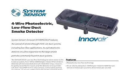
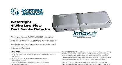
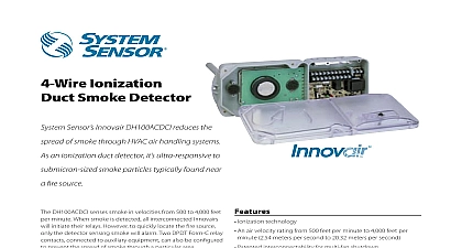
4 Wire Low Profile Smoke Detector Division of Pittway Ohio Avenue St Charles IL 60174 736 7672 Fax 630 377 6495 Available 4 wire Ionization Detector 4 wire Photoelectronic Detector Outside mounting tabs Telescoping sampling tube Built in reset button Interconnectability for multi fan shutdown up to ten handlers Cover tamper trouble signal Easy to clean 24 VAC DC or 120 240 VAC operation High Low voltage barrier Ion or photo models available Remote test station option Remote sounder option Air velocity rating from 500 to 4000 FPM Equipped with two DPDT Form C relay contacts Easy and quick mounting to round or rectangular ducts 1 wide Textured cover for convenient visual inspection UL 268A listed 3 year warranty Weight Range inches 14 cm inches 7 cm lbs 1.7 kg to 131 cid 176 F to 55 cid 176 C Patent pending Sensor DH100ACDC 4 wire duct duct smoke is available as either an ionization or model This new design allows for simplified and maintenance or a change in application removing the duct housing The DH100ACDC air currents passing through a duct and gives performance for management of fans blowers air conditioning systems preventing the spread of smoke and fire gases through the protected area Duct smoke detectors have specific limitations DETECTORS ARE a substitute for an open area smoke detector a substitute for early warning detection and a replacement for a building regular fire system to NFPA 72 and 90A for additional duct detector information Range Duct Velocity to 93 relative humidity to 4000 ft min System Sensor 1 98 document is not intended to be used for installation purposes Specifications air duct smoke detector shall be a System Sensor DH100ACDC Series Duct Smoke Detector The housing shall be UL listed per UL 268A for use in air handling systems The detector operate at air velocities of 500 feet per minute to feet per minute The unit shall be capable of up to ten 10 air handling systems when with other detectors The detector shall be of providing a trouble signal in the event that the cover is removed It shall be capable of local testing magnetic switch or remote testing using the Remote Test Station The unit shall be reset by reset button or remote test station The duct detector shall incorporate an airtight smoke chamber in with UL 268A Standard for Smoke Detectors Duct Applications The housing shall be capable of to either rectangular or round ducts without brackets An integral filter system shall be to reduce dust and residue effects on detector housing thereby reducing maintenance and servicing tubes shall either be telescoping or be easily by passing through the duct housing after the is mounted to the duct The unit shall provide a separation of no less than 1 4 and or a physical between the high and low voltage terminals The shall meet all applicable NEC and NFPA regarding electrical junction boxes Terminal shall be of the strip and clamp method for 12 AWG wiring Ratings DH100ACDC Includes Detector VAC 50 60 Hz supply voltage capacitance voltage time with RTS451 time by power down up time response time Test 270 m F max 2.0 VAC min to 0.3 sec sec max sec max to 17 sec VDC m F max VDC min to 0.3 sec sec max sec max to 17 sec VAC min to 0.3 sec sec max sec max to 17 sec detector label See detector label detector label VAC 50 60 Hz VAC 50 60 Hz 20 VAC min to 0.3 sec 0.6 sec max sec max to 17 sec detector label Supply Voltage 29 VDC VAC 50 60 Hz VAC 50 60 Hz VAC 50 60 Hz REQUIREMENTS USING NO ACCESSORIES standby current alarm current RATINGS mA mA mA RMS mA RMS mA RMS mA RMS mA RMS mA RMS initiation contacts SPST 30 VDC resistive auxiliary contacts DPDT 30 VDC 250 VAC Alarm auxiliary contacts must switch 100 mA minimum at 5VDC Alarm auxiliary contacts shall not be to inititaing circuits of control panels Use the alarm initiation contact for this purpose CURRENT LOADS AT 24 VDC Max Max Max Max RTS451KEY Max contacts SPDT 30 VDC resistive NOTE When a unit is powered at the 120VAC or 220 240VAC input any of accessories may be used such that the given accessory loads are mA or less in the standby state mA or less in the alarm state 2 Wiring Guide INPUTS ACCEPT VDC 24 VAC 50 60 HZ VAC 50 60 HZ OR VAC 50 60 HZ POWER SOURCE APPROPRIATE TERMINALS EACH DETECTOR CONTACT RATINGS 30 VDC RESISTIVE 250 VAC MINIMUM 5 VDC INTENDED FOR TO CONTROL POWER INPUTS POWER INPUTS AUXILIARY CONTACTS FAN SHUTDOWN ETC AUXILIARY CONTACTS FAN SHUTDOWN ETC POWER SOURCE APPROPRIATE TERMINALS EACH DETECTOR SEE FOR POWER SUPPLY WIRING OF AUXILIARY REFER TO INSTRUCTIONS CONTACT MANUFACTURER THE SUPERVISORY RELAY NOW A FORM C CONTACT FOR APPLICATIONS STANDARD APPLICATIONS ONLY NO CONTACT IS USED AUXILIARY CONTACTS SHOWN IN CONTACTS TRANSFER DURING AS INDICATED BY THE ARROWS AUXILIARY CONTACTS SHOWN IN CONTACTS TRANSFER DURING AS INDICATED BY THE ARROWS CONTACT RATING A 30 VDC resistive TROUBLE CONTACTS TROUBLE CONTACTS CONTACTS CLOSED IN ALARM AND STANDBY OPEN WHILE DETECTOR HEAD OR POWER IS OR WHEN TAMPER FEATURE TIMES OUT OPEN SIGNAL TROUBLE CONDITION TO PANEL CONTACTS CLOSED IN ALARM AND STANDBY OPEN WHILE DETECTOR HEAD OR POWER IS OR WHEN TAMPER FEATURE TIMES OUT OPEN SIGNAL TROUBLE CONDITION TO PANEL SHOWN IN STANDBY CLOSE ALARM SHOWN IN STANDBY CLOSE ALARM LISTED 4 WIRE PANEL DETECTOR IN THE LOOP DETECTOR IN THE LOOP RESISTOR BY MANUFACTURER wiring diagram for 4 wire duct smoke detectors detectors powered from initiating circuit Signal Power N O COM Power Wiring diagram shown is for DH100ACDC 4 wire dectector system equipped without a control panel diagram for DH100ACDC to APA451 LED Alarm LED Power Wiring diagram shown is for 4 wire duct system equipped a control panel Signal Power N O COM Power diagram for DH100ACDC to RTS451KEY and feature 3 ionization duct detector photoelectronic duct detector ionization sensor board photoelectronic sensor head power board Information No sampling tube duct widths 1 sampling tube duct widths 2 sampling tube duct widths 4 sampling tube duct widths 8