System Sensor EPS10EXP Manual

File Preview
Click below to download for free
Click below to download for free
File Data
| Name | system-sensor-eps10exp-manual-9182467035.pdf |
|---|---|
| Type | |
| Size | 643.11 KB |
| Downloads |
Text Preview
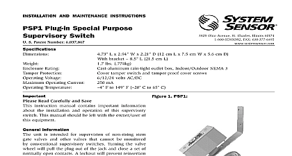
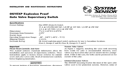
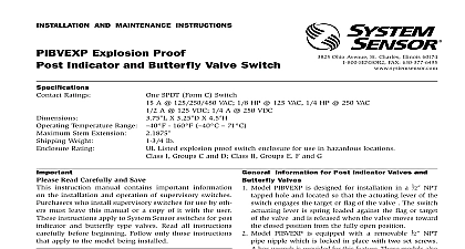
INSTALLATION AND MAINTENANCE INSTRUCTIONS Explosion Proof Pressure Switch Ratings A 1 2 HP 125 250 VAC A 6 12 24 VDC F to 160 PSI 20 PSI Type 4 Indoor or Outdoor Use Temperature Range Service Pressure Adjustment Range Rating Atmospheres Classification Class I Groups B C D Div 1 II Groups E F G Div 1 III Div 1 PSI throughout range Differential Ohio Avenue St Charles Illinois 60174 FAX 630 377 6495 Read Carefully and Save instruction manual contains important information the installation and operation of alarm pressure Purchasers who install switches for use by others leave this manual or a copy of it with the user all instructions carefully before installation following those instructions that apply to the model you are installing any alarm device be thoroughly familiar 72 Maintenance and Use of Signaling Systems of Sprinkler Systems 13 prevent ignition of hazardous atmospheres disconnect before removing cover Keep cover closed while cir are live Conduit runs must have sealing fittings con within 18 of the enclosure Back out cover tamper set screw and remove cover Fig 1 Mounting the Switch device is designed to be mounted in the upright or position side mounting is also acceptable 1 Pressure switch basic dimensions applicable NFPA standards local codes and the of the authority having jurisdiction to follow these directions may result in failure of the to report an alarm condition System Sensor is not for devices that have been improperly installed or maintained pressure changes a diaphragm actuates 2 snap action The pressure switch actuation is determined by settings ADJUST HEX HEAD SCREW ADJUSTMENT TURN INCREASE NPT 2 Typical piping diagram for EPS10EXP TO ALARM CIRCUIT FIRE ALARM PANEL ALARM OFF SYSTEM Y Y ALARM OFF SYSTEM TO ALARM CIRCUIT FIRE ALARM PANEL TO ALARM CIRCUIT FIRE ALARM PANEL Y ALARM OFF SYSTEM it where vibration shock and mechanical loading minimal Refer to piping diagram Figure 2 on page 2 Mount the device directly to the line via the 1 2 NPT connection The use of teflon pipe sealant is recommended Be sure the fitting is tight to prevent leaks Apply tightening torque to the brass hex portion of voltage Electrocution hazard Do not handle live AC or work on a device to which AC power is applied so may result in severe injury or death Wire the device in accordance with the National Code Two 1 2 NPT conduit entry holes have provided in the mounting base to accept explosion conduit fittings If necessary remove conduit entry with 3 8 square wrench Connect wiring to terminals see Figure 3 and Table 1 To Factory Settings 1 Electrical connections referenced at facto settings EPS10EXP AT 0 P S I AT 4 8 P S I HIGH TRIP PT SWITCHES ACTIVATE SIMULTANEOUSLY 3 Switch terminals 1 2 WIRE AS SHOWN FOR OF CONNECTION NOT ALLOW STRIPPED WIRE TO EXTEND BEYOND HOUSING DO NOT WIRES EPS10EXP device is pre adjusted at the factory to alarm 4 PSI on rising pressure see Table 2 Pressure switch may be adjusted in the field to obtain a different alarm response from 4 PSI to 20 PSI The switch an override feature on the adjustment mechanism to exceeding the 20 PSI max setting of the switch override feature carries with it a tolerance band that limit the upper adjustment to 16 PSI Care must be when setting the switch to ensure that the lower limit 4 PSI is not exceeded This will allow the switch to reset the 3 PSI differential stated Install pressure switch as stated in of instruction manual Attach pressure test to system Remove adjustment wheel cover and back off locking see Figure 1 to allow main adjustment wheel to freely Test trip point by slowly introducing pressure from the test source When trip point is found reduce to zero Rotate main adjustment wheel coun to increase pressure and retest until switch point is at the desired pressure setting 4 PSI Each tine on the wheel represents an approxi trip point change of 0.2 PSI One full rotation the trip point setting by approximately 2.5 PSI reset differential of approximately 3 PSI is typical the entire adjustment range of switch Retest the set point several times to ensure accuracy of Re seat locking screw Re install adjustment wheel cover 2 SETTINGS PSI Reset PSI Diff The sensor assembly is not field replaceable Do attempt to disassemble these parts If you have questions consult System Sensor System recommends careful consideration of the factors when specifying and installing Pressure Switches Always refer to the and Maintenance Instruction for spe recommendations on individual devices installing the unit Electrical ratings stated in literature and on name should not be exceeded Overload on switch can cause failure on the first Always wire devices according to national and electrical codes Install units away from shock and vibration Proper fittings should be used to prevent moisture entering the enclosure via the conduit Test all devices for proper operation after initial instal Perform preventive maintenance and periodic as required by the applicable NFPA standards not less than bi monthly Install a back up control for all critical applications control failure could endanger life or property backup control to serve as a high or low limit con is especially recommended for applications where runaway condition could result Do not mount unit where ambient temperatures will published limits Avoid impact or mechanical loading refer to insert for the Limitations of Fire Alarm Systems Limited Warranty Sensor warrants its enclosed pressure switch to be free from in materials and workmanship under normal use and service for a of three years from date of manufacture System Sensor makes no express warranty for this pressure switch No agent representative or employee of the Company has the authority to increase or alter obligations or limitations of this Warranty The Company obligation this Warranty shall be limited to the repair or replacement of any part the pressure switch which is found to be defective in materials or work under normal use and service during the three year period com with the date of manufacture After phoning System Sensor toll number 800 SENSOR2 736 7672 for a Return Authorization number defective units postage prepaid to System Sensor Return RA 3825 Ohio Avenue St Charles IL 60174 include a note describing the malfunction and suspected cause of The Company shall not be obligated to repair or replace units are found to be defective because of damage unreasonable use or alterations occurring after the date of manufacture In no shall t