System Sensor i3 Series Detectors with Sounder Relay

File Preview
Click below to download for free
Click below to download for free
File Data
| Name | system-sensor-i3-series-detectors-with-sounder-relay-2974136085.pdf |
|---|---|
| Type | |
| Size | 954.75 KB |
| Downloads |
Text Preview
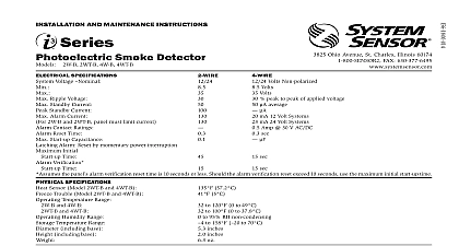
Smoke Detectors with and Relay Option Sensor i3 sounder and relay smoke detectors the guiding principles of installation ease and instant inspection in a series of conventional devices 85 dB sounder Form C relay Isolated thermal sensor Plug in design base included In line terminals Flexible mounting options Stop Drop Lock attachment to the base Removable cover and chamber Remote maintenance signaling Drift compensation and smoothing algorithms Simplified sensitivity measurement Dual color LEDs Listings ease Throughout the i3 series installation is simple its installer friendly base and plug in design The base a broad range of back box and direct mounting and provides ample space for pre wiring the device To the installation the i3 detector plugs into its base with a Stop Drop Lock action To reduce the likelihood of nuisance alarms all detectors are equipped with both drift compensation and algorithms These capabilities minimize both short and causes of nuisance alarms such as RF interference and accumulation When connected to the 2W MOD2 loop test module or an i3 Ready panel 2 wire i3 detectors can a remote maintenance signal when in a maintenance or trouble condition To measure the sensitivity of any i3 detector SENS RDR displays the reading in terms of percent per foot within seconds inspection i3 has red and green LEDs to simplify local indication during power up standby alarm maintenance freeze trouble conditions When in alarm i3 sounder models an 85 dB temporal tone If connected to the RRS MOD relay synchronization module all i3 sounders on the loop activate when one detector is in alarm The RRS MOD also i3 sounder output to ensure a clear audible signal the application call for differentiating between a local and general alarm the i3 line offers an isolated thermal model which a local alarm when smoke is detected and a general alarm the thermal sensor is activated Smoke Detector Specifications Specifications Voltage Ripple Voltage Current Standby Current Alarm Current Contact Ratings C Contact Ratings Specifications Temperature Humidity Sensor Trouble Terminals including Weight Pressure Output 12 24 V non polarized 8.5 V to 35 V 10 V to 35 V of applied voltage peak to peak 50 maximum average 50 maximum average 100 n a 2WTR B 130 mA limited by control 130 mA 4WTA B 4WTR B 35 mA 4WITAR B 50 mA Power Non Reverse Polarity 130 limited by panel Reverse Polarity Power mA for the 2WTA B in alarm 12 mA for all 2WTA B units on the loop Add 25 mA the RRS MOD reversing relay alarm current n a 0.5 A 30 V AC DC A 30 V AC DC to 100 0 to 37.8 to 95 RH non condensing 57.2 fixed 5 nominal AWG inches 134 mm diameter 2.0 inches mm height oz 200 g dBA models 2WTA B 4WTA B 4WTAR B 4WITAR B only octagonal back box 4 inch octagonal box single gang back box 4 inch square box with a plaster ring direct mount to Information Current mA max limited by panel mA max limited by panel mA mA mA mA Modes Mode up LED every seconds LED every 10 LED seconds seconds every 5 every 5 every 10 of Sequence for LED Indication LED Specifications detector shall be a System Sensor i3 Series model number to Underwriters Laboratories UL 268 for Fire Protection Signaling The detector shall be a combination photoelectric thermal with a sounder model 2WTA B 4WTA B a Form C relay model a combination sounder relay model 4WTAR B or an isolated model 4WITAR B The detector shall include a base for mounting to 3 and 4 inch octagonal single gang 4 inch square back boxes with a plaster ring or direct mount to the using drywall anchors Wiring connections shall be made by means SEMS screws The detector shall allow pre wiring of the base and the shall be a plug in type The detector shall have a nominal sensitivity 2.5 percent per foot as measured in the UL smoke box The detector be capable of automatically adjusting its sensitivity by means of drift and smoothing algorithms The detector shall provide dual LED indication that blinks to indicate power up normal standby out of alarm and freeze trouble conditions When used in conjunction the 2W MOD2 module 2 wire models shall include a maintenance to indicate the need for maintenance at the alarm control panel and provide a loop testing capability to verify the circuit without testing each individually When used in conjunction with the RRS MOD module i3 sounder models on a loop shall sound when one sounder alarms all shall synchronized and all sounders may be silenced from the panel relay synchronization module loop test maintenance module reader tool adapter bracket Ohio Avenue St Charles IL 60174 800 SENSOR2 Fax 630 377 6495 System Sensor specifications subject to change without notice Visit systemsensor com for product information including the latest version of this data sheet 6 09 2170