System Sensor i3 Series Smoke Detectors Manual

File Preview
Click below to download for free
Click below to download for free
File Data
| Name | system-sensor-i3-series-smoke-detectors-manual-1960437852.pdf |
|---|---|
| Type | |
| Size | 826.30 KB |
| Downloads |
Text Preview
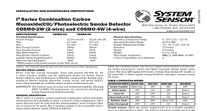
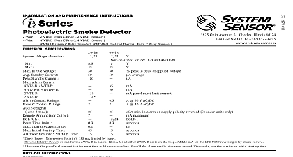
INSTALLATION AND MAINTENANCE INSTRUCTIONS Smoke Detector 2W B 2WT B 4W B 4WT B Ohio Avenue St Charles Illinois 60174 FAX 630 377 6495 Volts Non polarized Volts Volts peak to peak of applied voltage average mA 12 Volt Systems mA 24 Volt Systems Amp 30 V AC DC sec SPECIFICATIONS Voltage Ripple Voltage Standby Current Standby Current Alarm Current 2W B and 2WT B panel must limit current Contact Ratings Reset Time Start up Capacitance Alarm Reset by momentary power interruption Initial Start up Time Verification Start up Time the panel alarm verification reset time is 10 seconds or less Should the alarm verification reset exceed 10 seconds use the maximum initial start up time SPECIFICATIONS Sensor Model 2WT B and 4WT B Trouble Model 2WT B and 4WT B Temperature Range 2W B and 4W B 2WT B and 4WT B Humidity Range Temperature Range including base including base to 120 0 to 49 to 100 0 to 37.8 to 95 RH non condensing to 158 to 70 inches inches oz 57.2 5 sec sec INSTALLING read thoroughly System Sensor Applications Guide for System Smoke SPAG91 which provides detailed information on detector spacing zoning wiring and special applications This manual is available at www systemsensor com s This manual shall be left with the owner user of this equipment This detector must be tested and maintained regularly following 72 requirements At a minimum cleaning should be performed annually DESCRIPTION 2W B and 2WT B are 2 wire photoelectric smoke detectors models and 4WT B are 4 wire photoelectric smoke detectors All models in a state of the art optical sensing chamber and an advanced micro The microprocessor allows the detector to automatically adjust its back to the factory setting when it becomes more sensitive due to settling in its chamber In order for this feature to work prop the chamber must never be opened while power is applied to the smoke This includes cleaning maintenance or screen replacement Should become necessary the screen sensing chamber is field replaceable Mod 2WT B and 4WT B also feature a restorable built in fixed temperature thermal detector and are also capable of sensing a freeze condition if temperature is below 41 i3 Series detectors are designed to provide open area protection Two wire must be used with compatible UL Listed panels only used with an i3 Series compatible control panel or the i3 Series 2W module refer to installation manual D500 46 00 the 2W B and 2WT B capable of generating a needed signal The 2W MOD2 can a need for cleaning replacement or a freeze condition 2WT B only the control panel or module of the 2W B 2WT B 4W B and 4WT B detectors is simplified by use of a mounting base that may be pre wired to the system allowing the to be easily installed or removed The mounting base installation is simplified by the incorporation of features compatible with drywall LEDs on the detector provide a local visual indication of the detector status 1 DETECTOR LED MODES LED 10 sec 5 sec standby of sensitivity Trouble an initial power up delay the red and green LEDs will blink synchro once every ten seconds It will take approximately 80 seconds for the to finish the power up cycle see Table 2 LED 10 sec 5 sec 10 sec 2 POWER UP SEQUENCE FOR LED STATUS INDICATION seconds LED Status Indication LED Status Indication minutes excessive electrical noise is present to Electrical Specifications for start up time in conjunction with panel verification If during power up the detector determines there is excessive electri noise in the system such as those caused by improper grounding of the or the conduit both LEDs will blink for up to 4 minutes before display detector status see Table 2 power up has completed and the detector is functioning normally within listed sensitivity range the green LED blinks once every five seconds If the is in need of maintenance because its sensitivity has shifted outside listed limits the red LED blinks once every five seconds When the detec is in the alarm mode the red LED latches on The LED indication must not used in lieu of the tests specified under Testing In a freeze trouble condi the red LED will blink once every 10 seconds See Table 1 measure the detector sensitivity the i3 Series Model SENS RDR Infrared Reader tool should be used See Figure 4 2W B and 2WT B also include an output that allows an optional Model Remote Annunciator to be connected i3 Series detector is supplied with a mounting base that can be mounted To a single gang box or To a 31 or 4 inch octagonal box or To a 4 inch square box with a plaster ring or Direct mount or to ceiling using drywall fasteners See Figure 2 1 MOUNTING OF DETECTOR i3 Series heads and bases are keyed so that a 2 wire head will only mount a 2 wire base and a 4 wire head will only mount to a 4 wire base The and bases are clearly identified as either 2 wire or 4 wire When mount the i3 Series ensure that the head is mounted to the correct base FEATURE i3 Series detectors include a tamper resistant feature that prevents re from the mounting base without the use of a tool To engage the tam feature cut the small plastic tab located on the mounting base 2 and then install the detector To remove the detector from the base it has been made tamper resistant use a small screwdriver to depress the tamper release tab located on the skirt of the mounting base and turn detector counterclockwise 2 TAMPER RESISTANT FEATURE MOUNT OFF TAB TAMPER LOCK TAB NOT INSTALL DETECTORS IN THE FOLLOWING AREAS In or near areas where particles of combustion are normally present as kitchens in garages vehicle exhaust near furnaces hot water or gas space heaters In very cold or very hot areas In wet or excessively humid areas or next to bathrooms with showers In dusty dirty or insect infested areas Near fresh air inlets or returns or excessively drafty areas Air condition heaters fans and fresh air intakes and returns can drive smoke from the detector NFPA 72 the local Authority Having Jurisdiction AHJ and or ap codes for specific information regarding the spacing and placement smoke detectors detectors are not to be used with detector guards unless the combina has been evaluated and found suitable for that purpose INSTALLATION GUIDELINES wiring must be installed in compliance with the National Electrical Code state and local codes and any special requirements of the local Having Jurisdiction wire gauges should be used The conductors used to connect smoke to the alarm control panel and accessory devices should be color to reduce the likelihood of wiring errors Improper connections can a system from responding properly in the event of a fire screw terminals in the mounting base will accept 14 gauge wire For system performance all wiring should be installed in separate grounded do not mix fire alarm system wiring in the same conduit as any other wiring Twisted pair may be used to provide additional protection extraneous electrical interference connections are made by stripping approximately 1 of insulation the end of the feed wire inserting it into the proper base terminal and the screw to secure the wire in place COMPATIBILITY Sensor two wire smoke detectors are