System Sensor i4 Series CO Smoke Detectors Manual

File Preview
Click below to download for free
Click below to download for free
File Data
| Name | system-sensor-i4-series-co-smoke-detectors-manual-8103245967.pdf |
|---|---|
| Type | |
| Size | 1.43 MB |
| Downloads |
Text Preview
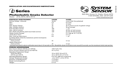
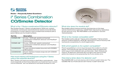
INSTALLATION AND MAINTENANCE INSTRUCTIONS Series Combination Carbon Smoke Detector 2 wire and COSMO 4W 4 wire Specifications volts DC Voltage volts volts Startup Current Standby Current Alarm Current Reverse Polarity Current Signal Supplemental Start up Capacitance requires a UL listed sounder on the NAC circuit volts DC volts volts Spcecificaitons Temperature Range Humidity Range Temperature Range Gauge Acceptance Compatibility Zone Identifier Ohio Avenue St Charles Illinois 60174 FAX 630 377 6583 50 C 32 122 F RH 70 C 14 158 F inches inches oz 261 g 22 AWG Max 14 AWG This manual shall be left with the owner user of this equipment INSTALLATION read this manual thoroughly along with manual I56 3871 for the series interface module and the Application Guides for System Sensor SPAG91 and CO Detectors COAG103 which provide detailed infor on detector spacing placement zoning wiring and special applica These manuals are available online at www systemsensor com This detector must be tested and maintained regularly following 72 NFPA 720 requirements At a minimum cleaning and should be performed annually DESCRIPTION i4 series is a plug in system connected combination carbon monoxide detector It is available in either a 2 wire or 4 wire configuration The i4 detectors must be used with the corresponding i4 series Interface Mod to connect to the panel The i4 interface module is also compatible with i3 smoke detector model 2WTA B or 4WTA B Features Photoelectric smoke sensor Drift compensation and noise rejection algorithms Red smoke LED indicator Smoke test switch Features Field replaceable electrochemical CO sensor RealTest functional test capable Blue CO LED indicator Sensor end of life notification Annunciation Local integral sounder Polarity reversal and Maintenance Stop Drop N Lock plug in base SEMS wiring terminals COSMO 2W designed for 2 wire i4 Zone type COSMO 4W designed for 4 wire i4 Zone type SENS RDR sensitivity reader compatible with extended range Removable cover for cleaning Replaceable screen Features Green supervisory LED Listed to UL standards 268 and 2075 ANNUNCIATON i4 series detector has three visible LED Green Red and Blue The green is a supervisory LED it blinks during power on reset and during normal It is extinguished during smoke maintenance CO trouble smoke and CO alarm events The red LED signals smoke events it blinks dur smoke maintenance events and lights constantly during smoke alarm The blue LED signals CO events it blinks blue during CO trouble or end of life it blinks rapidly during RealTest and lights constant during alarm 1 OPERATION MODES MODE GREEN LED standby 5 Sec LED LED Smoke CO Smoke CO Mode CO is Sprayed 1 Sec 3 4 3 4 feature When the sensor supervision is in a trouble condition as a detector that is dirty the detector will send a trouble signal to the then to the FACP Depending on the issue the detector must then be or replaced sensor end of life timer feature When the CO sensor has passed end of a trouble signal will be sent to the module then to the FACP This indicates the CO sensor inside the detector must be replaced If unresolved for 30 the detector will chirp intermittently The typical life of the CO sensor ten years from the date of manufacture it is recommended to periodically the by sticker located on the replaceable CO cell GUIDELINES Detector should be at least 12 inches from any wall Detector should be no closer than 6 inches from ceiling Do not install outdoors or in any environment that does not comply with detector environmental specifications Install in accordance with NFPA 72 and 720 standards NFPA 72 and define standards for both commercial and residential installation of and CO detectors State and local laws involving CO detection also be considered If the installation can be interpreted as residential consult the section NFPA 720 that outlines residential applications Chapter 9.4.1.1 for states that carbon monoxide alarms or detectors shall be in as follows Outside each separate dwelling unit sleeping area in the immediate of the bedroom On every level of a dwelling unit including basements Consult NFPA 72 the local Authority Having Jurisdiction AHJ and applicable codes for specific information regarding the spacing and of smoke detectors Do not install detectors in the following areas In or near areas where particles of combustion are normally present such as in garages near furnaces hot water heaters or gas space heaters In very cold or very hot areas In wet or excessively humid areas or next to bathrooms with showers In dusty dirty or insect infested areas Near fresh air inlets or returns or excessively drafty areas Air con heaters fans and fresh air intakes and returns can drive away from the detector This unit is UL listed as containing a supplemental sounder and should be used as a primary sounder for evacuation 1 ALARM LOCATION DIAGRAM FOR RESIDENTIAL APPLICATION MONOXIDE SMOKE ALARM FOR MULTI LEVEL RESIDENCE i4 detector can be ceiling mounted or wall mounted To a single gang box 2 in by 4 in box 3 in or 4 in octagonal or 3 or 4 in round ceiling Direct mount to ceiling or to wall using drywall fasteners 2 MOUNTING OF DETECTOR INSTALLATION GUIDELINES wiring must be installed in compliance with the NFPA 70 standards Na Electrical Code applicable state and local codes screw terminals in the mounting base will accept 14 22 gauge wire Wire are made by stripping approximately 3 8 to of insulation from 3 COSMO 2W WIRING DIAGRAM CIRCUITS ARE SUPERVISED TRIGGERS AND MUST POWER LIMITED end of the feed wire inserting it into the proper base terminal and tight the screw to secure the wire in place Do not put wires more than 2 apart under the same clamping plate power from alarm control unit or initiating device circuits before installing detectors Remove detector from packaging and separate the base from the detector head Wire the detector base screw terminals Screw the base of the detector onto an electrical box or to the surface of wall or ceiling using the hardware included in the packaging Attach the detector head to the base by applying light pressure and rotat clockwise The detector will lock in place when properly aligned After all detectors have been installed apply power to the alarm control Refer to Table 3 for time to LED stabilization Once stabilized the LED will blink once every 5 seconds Test each detector as described in the Testing section Notify the proper authority that the system is in operation 72 recommends the installation of detectors only after completing construction or other dust producing activity 2 LED INDICATION DURING POWER UP SEQUENCE LED Power LED LED on Reset 5 Sec 5 Sec 5 Sec 3 POWER UP TIME TO FIRST ALARM LED STABILIZATION Up Time up time after second reset Indication time LED indication time Seconds Seconds 45 seconds 55 seconds 55 seconds 268 seconds detector must be tested after installation


