System Sensor M500M-4-20 Manual
File Preview
Click below to download for free
Click below to download for free
File Data
| Name | system-sensor-m500m-4-20-manual-1356740829.pdf |
|---|---|
| Type | |
| Size | 1.43 MB |
| Downloads |
Text Preview
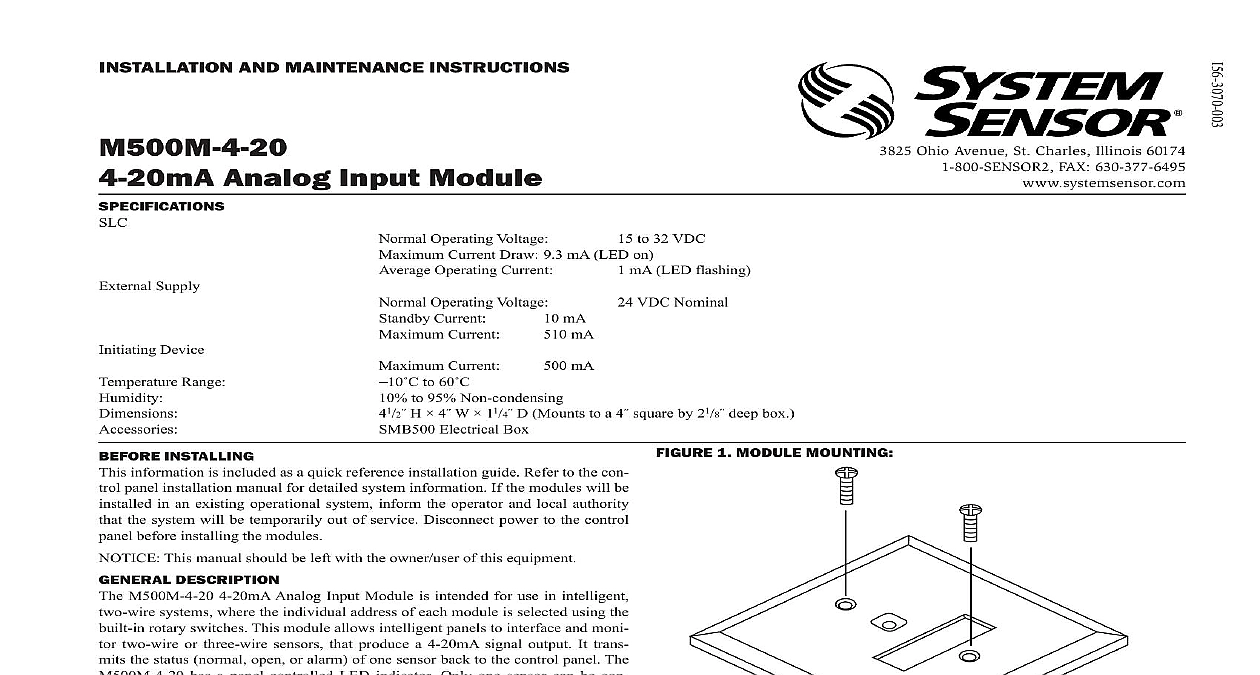
I Ohio Avenue St Charles Illinois 60174 FAX 630 377 6495 AND MAINTENANCE INSTRUCTIONS Analog Input Module Supply Device Range Operating Voltage Current Current Operating Voltage Current Draw 9.3 mA LED on Operating Current to 32 VDC mA LED flashing VDC Nominal mA mA mA Current to 60 to 95 Non condensing H 4 W 11 4 D Mounts to a 4 square by 21 8 deep box Electrical Box 1 MODULE MOUNTING INSTALLING information is included as a quick reference installation guide Refer to the con panel installation manual for detailed system information If the modules will be in an existing operational system inform the operator and local authority the system will be temporarily out of service Disconnect power to the control before installing the modules This manual should be left with the owner user of this equipment DESCRIPTION M500M 4 20 4 20mA Analog Input Module is intended for use in intelligent systems where the individual address of each module is selected using the rotary switches This module allows intelligent panels to interface and moni two wire or three wire sensors that produce a 4 20mA signal output It trans the status normal open or alarm of one sensor back to the control panel The has a panel controlled LED indicator Only one sensor can be con to the M500M 4 20 REQUIREMENTS ensure proper operation this module shall be connected to a listed compatible control panel only M500M 4 20 mounts directly to 4 inch square electrical boxes see Figure 1 box must have a minimum depth of 21 8 inches Surface mounted electrical boxes are available from System Sensor All wiring must conform to applicable local codes ordinances and regula This module is intended for powerlimited wiring only Install module wiring in accordance with the job drawings and appropriate wir diagrams the address on the module per job drawings Secure module to electrical box supplied by installer as shown in Figure 1 2 4 20mA MODULE 3 WIRE CONFIGURATION VDC POWER VDC POWER ISOLATED POWER PER NFPA 70 864 LISTED FOR PROTECTION USE WITH BACKUP 4 20mA 3 4 20mA MODULE 2 WIRE CONFIGURATION NEXT VDC POWER NEXT VDC POWER SUPPLY REGULATED LIMITED PER 70 UL 864 LISTED FIRE PROTECTION USE WITH BACKUP 4 20mA DEVICE SENSE NEXT PANEL OR DEVICE LINE CIRCUIT SLC VDC MAX PAIR RECOMMENDED NEXT WIRING MUST POWER LIMITED NOT LOOP WIRE UNDER TERMINALS ALL WIRE RUNS TO PROVIDE OF CONNECTIONS PANEL OR DEVICE LINE CIRCUIT SLC 32 MAX PAIR RECOMMENDED WIRING WIRING MUST POWER LIMITED NOT LOOP WIRE UNDER TERMINALS ALL WIRE RUNS TO PROVIDE OF CONNECTIONS LIMITED WARRANTY Sensor warrants its enclosed smoke detector to be free from defects in materials workmanship under normal use and service for a period of three years from date manufacture System Sensor makes no other express warranty for this smoke detec No agent representative dealer or employee of the Company has the authority to or alter the obligations or limitations of this Warranty The Company obligation this Warranty shall be limited to the repair or replacement of any part of the smoke which is found to be defective in materials or workmanship under normal use service during the three year period commencing with the date of manufacture phoning System Sensor toll free number 800 SENSOR2 736 7672 for a Return number send defective units postage prepaid to Honeywell 12220 Rojas Suite 700 El Paso TX 79936 USA Please include a note describing the malfunc and suspected cause of failure The Company shall not be obligated to repair or units which are found to be defective because of damage unreasonable use or alterations occurring after the date of manufacture In no case shall the be liable for any consequential or incidental damages for breach of this or any Warranty expressed or implied whatsoever even if the loss or damage is caused by Company negligence or fault Some states do not allow the exclusion or limitation of or consequential damages so the above limitation or exclusion may not apply you This Warranty gives you specific legal rights and you may also have other rights vary from state to state STATEMENT device complies with part 15 of the FCC Rules Operation is subject to the following two conditions 1 This device may not cause harmful interference and 2 this device must any interference received including interference that may cause undesired operation This equipment has been tested and found to comply with the limits for a Class A digital device pursuant to Part 15 of the FCC Rules These limits are designed to provide protection against harmful interference when the equipment is operated in a commercial environment This equipment generates uses and can radiate radio frequency and if not installed and used in accordance with the instruction manual may cause harmful interference to radio communications Operation of this equipment in a residential is likely to cause harmful interference in which case the user will be required to correct the interference at his own expense System Sensor 03 11