System Sensor M500X Manual

File Preview
Click below to download for free
Click below to download for free
File Data
| Name | system-sensor-m500x-manual-7643915802.pdf |
|---|---|
| Type | |
| Size | 1.15 MB |
| Downloads |
Text Preview
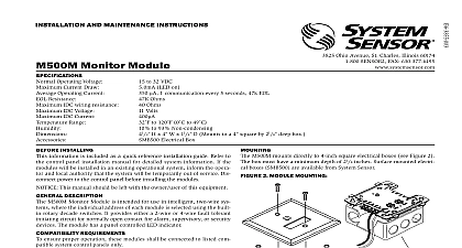
INSTALLATION AND MAINTENANCE INSTRUCTIONS FAULT ISOLATOR MODULE Operating Voltage Current Current Draw Range 32 VDC not isolating device in isolation to 120 0 to 49 to 93 Non condensing H 4 W 1 4 D Mounts to a 4 square by 21 8 deep box 3825 Ohio Avenue St Charles Illinois 60174 FAX 630 377 6495 INSTALLING information is included as a quick reference installation guide Refer to control panel installation manual for detailed system information If the will be installed in an existing operational system inform the opera and local authority that the system will be temporarily out of service Dis power to the control panel before installing the modules This manual should be left with the owner user of this equipment DESCRIPTION Fault Isolator Modules enable part of the communications loop to con operating when a short circuit occurs on it An LED indicator blinks in normal condition and turns on during a short circuit condition The mod will automatically restore the entire communications loop to the normal when the short circuit is removed REQUIREMENTS ensure proper operation these modules shall be connected to listed com system control panels only The number of devices that may be installed between fault isolator will vary based on the types of devices being isolated Contact the alarm control panel manufacturer for the isolator load ratings of indi devices modules mount directly to 4 square electrical boxes The box must a minimum depth of 21 8 All wiring must conform to applicable local codes ordinances and Install module wiring in accordance with the job drawings and the diagram in Figure 1 module to electrical box supplied by installer Terminal wire gage 12 18 AWG 1 FAULT ISOLATOR MODULE WIRING ISOLATOR MODULE LINE CIRCUIT SLC VDC MAX WIRING SHOWN IS SUPERVISED LISTED COMPATIBLE PANEL ISOLATOR MODULE OF DEVICES ARE SEPARATED BY FAULT ISOLATOR ANY COMBINATION OF COMPATIBLE LISTED MAY BE MIXED WITHIN A GROUP PAIR OF FAULT ISOLATOR MODULES WILL DISCONNECT A OF DEVICES IF A SHORT CIRCUIT OCCURS ON THE LINE CIRCUIT WITHIN THAT GROUP ISOLATOR MODULE LIMITED WARRANTY Sensor warrants its enclosed smoke detector to be free from defects in materials workmanship under normal use and service for a period of three years from date manufacture System Sensor makes no other express warranty for this smoke detec No agent representative dealer or employee of the Company has the authority to or alter the obligations or limitations of this Warranty The Company obligation this Warranty shall be limited to the repair or replacement of any part of the smoke which is found to be defective in materials or workmanship under normal use service during the three year period commencing with the date of manufacture phoning System Sensor toll free number 800 SENSOR2 736 7672 for a Return number send defective units postage prepaid to Honeywell 12220 Rojas Suite 700 El Paso TX 79936 USA Please include a note describing the malfunc and suspected cause of failure The Company shall not be obligated to repair or units which are found to be defective because of damage unreasonable use or alterations occurring after the date of manufacture In no case shall the be liable for any consequential or incidental damages for breach of this or any Warranty expressed or implied whatsoever even if the loss or damage is caused by Company negligence or fault Some states do not allow the exclusion or limitation of or consequential damages so the above limitation or exclusion may not apply you This Warranty gives you specific legal rights and you may also have other rights vary from state to state STATEMENT device complies with part 15 of the FCC Rules Operation is subject to the following two conditions 1 This device may not cause harmful interference and 2 this device must any interference received including interference that may cause undesired operation This equipment has been tested and found to comply with the limits for a Class A digital device pursuant to Part 15 of the FCC Rules These limits are designed to provide protection against harmful interference when the equipment is operated in a commercial environment This equipment generates uses and can radiate radio frequency and if not installed and used in accordance with the instruction manual may cause harmful interference to radio communications Operation of this equipment in a residential is likely to cause harmful interference in which case the user will be required to correct the interference at his own expense System Sensor 03 11