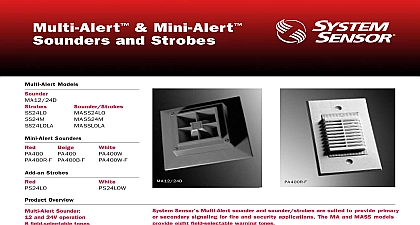
System Sensor mini alert sounder strobes

File Preview
Click below to download for free
Click below to download for free
File Data
| Name | system-sensor-mini-alert-sounder-strobes-7412058936.pdf |
|---|---|
| Type | |
| Size | 811.79 KB |
| Downloads |
Text Preview
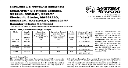
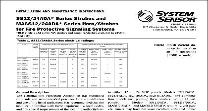
INSTALLATION AND MAINTENANCE INSTRUCTIONS PS12LO W PS12M W and PS24M W Mini Sounders and Strobes models add suffix available in 24VDC only SENSOR Division of Pittway 3825 Ohio Avenue St Charles Illinois 60174 FAX 630 377 6495 Sounder Voltage Drain Range Output Strobe Voltage Current Drain Panel Voltage Light Output Viewing Angle Fig 2 absolute min to 33VDC absolute max mA at 12 volts mA at 24 volts to 60oC 14oF to 140oF C to 49 cid 176 C 32 cid 176 F to 120 cid 176 F with strobe added than 90 dBA measured in anechoic room at 10 feet 24 volts Figure 1 for other voltages 82 dBA minimum measured in UL reverbarant room dBA minimum with strobe VDC VDC 30 VDC 30 VDC 30 VDC 30 VDC mA mA mA mA mA mA candela candela candela candela candela candela 1 2 100 C to 49 cid 176 C 32 cid 176 F to 120 cid 176 F Range no circumstances can the PS24 voltage exceed 33VDC or be less than 18VDC no circumstances can the PS12 voltage exceed 18.7VDC or be less than 9.6VDC calculate battery requirements use current values shown above However note that there is an in rush current associated with power up The information in Figures 3 and 4 is useful when selecting fuse values Figure 3 shows 12V strobe in rush current typically peaks at 3A and drops to nominal in 600m S In a 24V strobe Figure 4 in rush typically peaks at 7.0A and drops to nominal in 800m S 3 12 volt strobe in rush current Figure 4 24 volt strobe in rush current Information National Fire Protection Association has published codes and recommended practices for the installation and of the above appliances Therefore the installer must be fa with these requirements with local codes and any special of the authority having jurisdiction PA400 PA400W white and PA400R red Piezo Alert electronic and optional supplementary signal strobes are intended be connected to the alarm indicating circuit of a UL listed 12 or VDC fire alarm control panel The models PS12 and PS24 op strobe additions to the PA400 require a 12 VDC or 24 VDC respectively and are able to operate from a full wave recti unfiltered supply Notes wiring must be in compliance with all codes and must not be such length or wire size that would cause the appliance to op outside of its published specifications The appliances must be tested after installation in accordance with the control manufacturer test procedure Do not loop wires under terminal screws Wires the device to the panel must be broken at the screw terminal in order to maintain electrical Manuals Online Sounders The PA400 is intended for mounting to a standard 2 1 2 deep box which allows sufficient clearance for conduit The PA400 is compatible with DC line supervision The Piezo is polarized and has terminals marked with polarity Ap positive supply voltage to the terminal and negative voltage to the terminal See Figure 5 Mount the appliance to the electrical outlet box using the two screws supplied Field repair of the PA400 should not be attempted Return to for repair or replacement or PS24 Strobes optional strobes are interconnected to the PA400 by first re the two mounting screws from the sounder Use a small to punch out the skinned over areas as indicated in 6 Install the adapter plate on top of the sounder and screw combined sounder and adapter plate to the electrical outlet Make sure field wiring terminals are oriented in the upward when mounted in the outlet box Next slide the strobe into the slots in the plates The positive solder lug may be red or marked with a plus sign This lug must be in slot closest to the field wiring terminals Grasp the catch area each end of the strobe and squeeze while applying inward Make sure the strobe catches fully engage the slots in the plate and that no gap appears at the interface between the and adapter plate I I I Shown with control panel in alarm Panel polarity in supervisory condition 5 6 Limitations of Sounders and Strobes Sensor sounder and signal strobe is designed to provide fire and hazard warning strobe is for supplementary signaling use only sounder or sounder strobe combination will not work without The sounder or sounder strobe gets its power from the fire or se panel monitoring the alarm system If power is cut off for any rea the sounder or sounder strobe combination will not provide the audible or visual warning sounder may not be heard The loudness of the sounder meets or current Underwriters Laboratories standards however the may not alert a sound sleeper or one who has recently used drugs has been drinking alcoholic beverages The sounder may not be heard if is placed in an area which is isolated by a closed door or if it is located a different floor from the person in hazard or if placed too far away to heard over the ambient noise such as traffic air conditioners machin or music appliances that may prevent alert persons from hearing the The sounder may not be heard by persons who are hearing im signal strobe may not be seen The electronic visual warning signal or exceeds current Underwriters Laboratories standard 1638 The warning signal is suitable for direct viewing and must be installed an area where it can be seen by building occupants The strobe not be installed in direct sunlight or areas of high light intensity the visual flash might be disregarded or not seen The strobe may be seen by the visually impaired signal strobe may cause seizures Individuals who have a positive response to visual stimuli with seizures such as epileptics should prolonged exposure to environments in which strobe signals in this strobe are activated Limited Warranty Sensor warrants its enclosed sounder strobe to be free from de in materials and workmanship under normal use and service for a of three years from date of manufacture System Sensor makes no express warranty for this sounder strobe No agent representative or employee of the Company has the authority to increase or alter obligations or limitations of this Warranty The Company obligation this Warranty shall be limited to the repair or replacement of any part of sounder strobe which is found to be defective in materials or work under normal use and service during the three year period com with the date of manufacture After phoning System Sensor toll number 800 SENSOR2 736 7672 for a Return Authorization number defective units postage prepaid to System Sensor Repair Depart RA 3825 Ohio Avenue St Charles IL 60174 Please a note describing the malfunction and suspected cause of failure Company shall not be obligated to repair or replace units which are to be defective because of damage unreasonable use modifica or alterations occurring after the date of manufacture In no case the Company be liable for any consequential or incidental damages breach of this or any other Warranty expressed or implied whatsoever if the loss or damage is caused by the Company negligence or fault states do not allow the exclusion or limitation of incidental or conse damages so the above limitation or exclusion may not apply to This Warranty gives you specific legal rights and you may also have rights which vary from state to state Manuals Online System Sensor 1996 AND MAINTENANCE INSTRUCTIONS Series Strobes with for Fire Protective Systems 1 PS12 24AD