System Sensor RMK400 Manual

File Preview
Click below to download for free
Click below to download for free
File Data
| Name | system-sensor-rmk400-manual-7085391264.pdf |
|---|---|
| Type | |
| Size | 612.12 KB |
| Downloads |
Text Preview
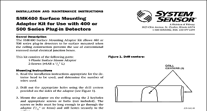
INSTALLATION AND MAINTENANCE INSTRUCTIONS Recessed Mounting Kit for use 100 and 200 Photoelectronic or 400 500 Series Plug in Detectors This manual should be left with the owner user this equipment 1 Division of Pittway 3825 Ohio Avenue St Charles Illinois 60174 FAX 630 377 6495 2 Top view of mounting bracket 3 Description RMK400 Recessed Mounting Kit is designed for use System Sensor 100 and 200 photoelectronic or 400 and Series plug in detectors As indicated in Figure 1 this kit provides for the recessed mounting of these on a junction box with flexible conduit on dry suspended ceilings and other similar surfaces All System Sensor smoke detectors can be made However the use of this capabil is NOT recommended with the RMK400 Mount Kit kit consists of Plastic Recess Mounting Ring Plastic Spacer Ring Metal Mounting Bracket Screws Type B No 8 Instructions a 4 1 2 inch 115 mm hole at the desired location the mounting surface a 4 1 2 inch junction box at the location of hole cut in step 1 Route all wiring to the box flexible conduit Be sure to allow sufficient and wiring to permit the wired box conduit to be pulled through the 4 1 2 hole the wiring through the box and attach the conduit the junction box the junction box as far as possible through the that was cut in step 1 Attach the Metal Mounting Bracket to the junction using the screw supplied with the junction box the electrical wiring around the Metal Bracket and the center holes in the Recess Mounting Ring Ring and the Detector Mounting Base See Fig 2 Align the holes in the B401 or B501 Detector Base and the holes in the plastic Recess Ring with the two small holes of the Metal Bracket Series photoelectronic detectors only Snap Spacer Ring into place in the Recess Mounting the two Type B No 8 screws supplied into the holes in the Metal Mounting Bracket and tighten until the assembly is just snug Do NOT tighten screws to the point where the Metal Mounting begins to deform this assembly into the mounting hole and hold in place while tightening the screws started in step 8 the assembly is retained in the mounting surface Wire the detector base following the instructions pro with the base Plug the detector into the base and rotate it clockwise it locks into the mounting base System Sensor 1996