System Sensor SA CH1224 and CH1224W Manual

File Preview
Click below to download for free
Click below to download for free
File Data
| Name | system-sensor-sa-ch1224-and-ch1224w-manual-5672049831.pdf |
|---|---|
| Type | |
| Size | 822.04 KB |
| Downloads |
Text Preview
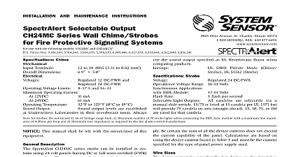
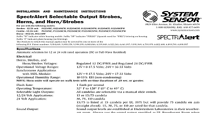
INSTALLATION AND MAINTENANCE INSTRUCTIONS Chime Sounder use with the following models 12 24 volt CH12 24 suffix for white models Products to which this manual applies may be covered by one or more of the following U S Patent Numbers 5,914,665 6,133,843 3825 Ohio Avenue St Charles Illinois 60174 FAX 630 377 6495 Regulated 12 DC FWR and Regulated 24 DC FWR Voltage Limits 8 and 16 Operating Current At 12VDC 31 mA At 24VDC 61 mA Temperature 32 to 120 0 to 49 Output Sound output levels are established at Underwriters Laboratories in their reverberant room Always use the sound UL 464 Private Mode specified as UL Reverberant Room when comparing products Description SpectrAlert series notification appliances are designed to meet the of most agencies governing these devices including NFPA National Fire Alarm Code UL CSFM MEA Also check with your Authority Having Jurisdiction for other codes or standards that may Chime Sounders are non synchronous and are not MDL compat Chime Sounder series can be installed in systems using 12 or 24 volt having DC or full wave rectified FWR power supplies This manual shall be left with the owner user of this equip Alarm System Considerations and Non Temporal Coded Signals American National Standards Institute and the National Fire Alarm require that all horns used for building evacuation installed after 1 1996 must produce Temporal Coded Signals Signals other than used for evacuation purposes do not have to produce the Temporal Signal Supply Considerations typically supply DC filtered voltage or FWR full wave rectified The system design engineer must calculate the number of units in a zone based on the type of panel supply Be certain the sum of the device currents does not exceed the current capability of the panel are based on using the device current found in the subsequent and must be the current specified for the type of panel power sup used The SpectrAlert Electronic Chime Sounder must be powered a non coded power supply This appliance is not intended use with a coded power supply Sizes designer must be sure that the last device on the circuit has sufficient to operate the device within its rated voltage When calculating voltage available to the last device it is necessary to consider the volt drop due to the resistance of the wire The thicker the wire the less voltage drop Generally for purposes of determining the wire size nec for the system it is best to consider all of the devices as the end of the supply circuit simulates case wire size resistance AWG solid AWG solid AWG solid AWG solid 8 ohms 1,000 ft 5 ohms 1,000 ft 3 ohms 1,000 ft 2 ohms 1,000 ft Assume you have 10 devices on a zone and each requires 50 mA and 2000 Ft of 14 AWG wiring total length outgoing return voltage at the end of the loop is 0.050 amps per device 10 devices 3 ohms 1,000 ft 2000 ft 3 volts drop If Class A wiring is installed the wire length may be up to 4 times single wire length in this calculation same number of devices using 12 AWG wire will produce only 2 volts The same devices using 18 AWG wire will produce 8 volts drop your panel manufacturer specifications as well as SpectrAlert voltage range to determine acceptable voltage drop Selection are factory set for high volume 1000Hz 1 second chime Tones be selected by making the appropriate settings on the DIP Switch on the printed circuit board The settings required for the available options are as follows 1 I56 0003 004R Chime Switch Settings Electronic Chime Current Draw 18 31 current draw varies with tones selected Current ratings per Sensor testing at 12VDC and 24VDC 1 second chime 1 second chime 1 second chime 1 4 second chime 1 4 second chime 1 4 second chime 3 chime 3 chime 3 chime Stroke Chime Stroke Chime Stroke Chime Continuous Temporal 3 Continuous Temporal 3 Chime Tones 1 Second Chime 1 4 Second Chime 3 Chime Stroke Chime 0 off LOW MED HIGH 500Hz Electromechanical and 3kHz Electromechanical 500Hz Electromechanical and 3kHz Electromechanical second Electronic Chime Sound Output Guide Tone 1.2K Repeating 1 Second Chime 1.0K Repeating 1 Second Chime 0.8K Repeating 1 Second Chime 1.2K Repeating 1 4 Second Chime 1.0K Repeating 1 4 Second Chime 0.8K Repeating 1 4 Second Chime 1.2K Temporal 3 Chime 1.0K Temporal 3 Chime 0.8K Temporal 3 Chime 1.2K Single Stroke Chime 1.0K Single Stroke Chime 0.8K Single Stroke Chime 3.0K Continuous Electromechanical 3.0K Temporal Electromechanical 0.5K Continuous Electromechanical 0.5K Temporal Electromechanical Volts Volts Volts Volts Factory default setting is 1.0K Repeating 1 Second Chime set at High volume chime models were only tested at the 8 17.5 and 16 33 Volt FWR DC limits This does not include the 80 low end or 110 high end limits 2 I56 0003 004R The chime is intended for mounting to a standard 11 2 deep single box which allows sufficient clearance for conduit entrance The chime is compatible with DC line supervision is polarized and terminals marked with polarity Apply positive supply voltage to terminal and negative supply voltage to the terminal See 1 Mount the chime to the electrical outlet box using the two mounting 2 Removal of horns and strobes from mounting remove units from mounting plates insert screwdriver as shown to snap While pushing in screwdriver to release the snap pull back the chime sounder Hinge the chime sounder module disengage the Rib and lift the chime sounder away from the mounting plate Field repair of the chime should not be attempted Return to factory SNAP LEVER REMOVAL TOOL supplied repair or replacement 1