System Sensor SA CH24MC and CH24MCW Manual

File Preview
Click below to download for free
Click below to download for free
File Data
| Name | system-sensor-sa-ch24mc-and-ch24mcw-manual-6874105923.pdf |
|---|---|
| Type | |
| Size | 827.73 KB |
| Downloads |
Text Preview
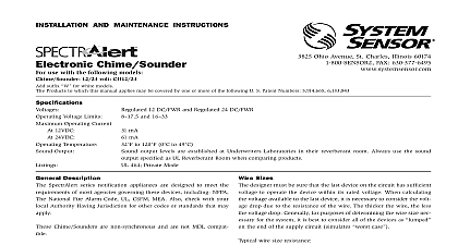
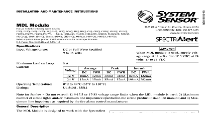
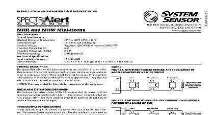
INSTALLATION AND MAINTENANCE INSTRUCTIONS Selectable Output Series Wall Chime Strobes Fire Protective Signaling Systems use with the following models CH24MC and CH24MCW Patent Nos 5,931,569 5.914,665 5,850,178 5,598,139 6,049,446 6,127,935 6,133,843 6,822,400 6,856,241 3825 Ohio Avenue St Charles Illinois 60174 FAX 630 377 6495 Chime Terminals Dimensions to 18 AWG 3.31 to 0.82 mm2 5.0 Regulated 12 DC FWR and 24 DC FWR and 16 Voltage Limits Operating Current At 12VDC mA mA At 24VDC to 120 0 to 49 Temperature Output output levels are established Underwriters Laboratories in their reverberant room Always the sound output specified as UL Reverberant Room when products UL S4011 Private Mode Chime UL S5512 Strobe 24 DC FWR Strobe Voltage Range 16 33 Volts Applications MDL Module Volts flash per second Rate Light Outputs candelas are selectable via a slide switch 15 75 is listed at 15 candela per UL 1971 but provide 75 candela on axis straight ahead 15 30 75 or 110 rated for that candela for Strobes Do not exceed 1 16 33 Voltage range limit 2 Maximum number of 70 strobe lights when connecting the MDL Sync module with a maximum line imped of 4 Ohms per loop and 3 Maximum line impedance as required by the fire alarm control manufacturer This manual shall be left with the owner user of this Description SpectrAlert CH24MC series strobe can be installed in sys using 24 volt panels having DC or full wave rectified FWR supplies The strobes can also be installed in applications synchronization MDL required or applications that do require synchronization no module required Please note the chime section is not synchronizable with the MDL SpectrAlert CH24MC series chime strobes are designed to the requirements of most agencies governing these devices NFPA ADA The National Fire Alarm Code UL Also with your local Authority Having Jurisdiction for other or standards that may apply The SpectrAlert CH24MC Series Chime Strobe must powered from a non coded power supply This is not intended for use with a coded power Alarm Considerations and Non Temporal Coded Signals American National Standards Institute and the National Alarm Code require that all horns used for building evacu installed after July 1 1996 must produce Temporal Coded Signals other than those used for evacuation purposes do have to produce the Temporal Coded Signal Supply Considerations For Strobes typically supply DC filtered voltage or FWR full wave voltage The system design engineer must calculate the of units used in a zone based on the type of panel sup Be certain the sum of all the device currents does not exceed current capability of the panel Calculations are based on the device current found in Table 3 and must be the current for the type of panel power supply used 8 ohms 1,000 ft 5 ohms 1,000 ft 3 ohms 1,000 ft 2 ohms 1,000 ft Sizes designer must be sure that the last device on the circuit has voltage to operate the device within its rated voltage calculating the voltage available to the last device it is to consider the voltage drop due to the resistance of the The thicker the wire the less the voltage drop Generally for of determining the wire size necessary for the system is best to consider all of the devices as on the end of supply circuit simulates case wire size resistance AWG solid AWG solid AWG solid AWG solid Assume you have 10 devices on a zone and each 50 mA average and 2000 Ft of 14 AWG wiring total return The voltage at the end of the loop 0.050 amps per device 10 devices 3 ohms 1,000 ft 2000 3 volts drop same number of devices using 12 AWG wire will produce only volts drop The same devices using 18 AWG wire will produce volts drop Consult your panel manufacturer specifications as as SpectrAlert operating voltage range to determine accept voltage drop If class wiring is installed the wire length may be up to times the single wire length in this calculation Selection are factory set for high volume 1.0K repeating 1 second Tones may be selected by making the appropriate settings the DIP Switch located on the printed circuit board The set required for the available tone options are as follows Chime Tones 1 Second Chime 1 4 Second Chime 1 SpectrAlert Chime Switch Settings 1 on 0 off 1 Second Chime 1 4 Second Chime 3 Chime Stroke Chime Continuous Temporal 3 Continuous Temporal 3 Switch 3 Chime Stroke Chime second 500Hz Electromechanical and 3kHz Electromechanical 500Hz Electromechanical and 3kHz Electromechanical 2 SpectrAlert Electronic Chime Sound Output Guide Volts Tone Repeating 1 Second Chime Repeating 1 Second Chime Repeating 1 Second Chime Repeating 1 4 Second Chime Repeating 1 4 Second Chime Repeating 1 4 Second Chime Temporal 3 Chime Temporal 3 Chime Temporal 3 Chime Single Stroke Chime Single Stroke Chime Single Stroke Chime Continuous Electromechanical Temporal Electromechanical Continuous Electromechanical Temporal Electromechanical Factory default setting is 1.0K Repeating 1 Second Chime set at High volume Volts Volts Volts chime section only tested at the 8 17.5 and 16 33 Volt FWR DC limits This does not include the 80 low end or 110 voltage limits 3 Strobe Current Draw Measurements All models were only tested at the 16 33 Volt FWR DC limits This does not include the 80 low end or 110 high end voltage limits No Setting Operating RMS Operating RMS Electronic Chime Current Draw 18 31 current draw varies with tones selected Current ratings per System Sensor testing at 12VDC and 24VDC Add current values when connecting in parallel strobe module the back box be located near an obstruction such as a the strobe module is field reversible Fig 1 1 Reversible strobe module REMOVE RIB strobe is on the mount chime strobe 6 32 screws inserted the holes on the left the mud ring strobe is on the mount chime strobe 6 32 screws inserted the holes on the right the mud ring reverse the strobe module insert screwdriver as shown in 3 to unlock snap While pushing in the screwdriver pull on the strobe module Hinge the strobe module disengage Locking Rib and lift the module away from the mounting Turn the module so that i