System Sensor SA RP1224ADA Series Manual
File Preview
Click below to download for free
Click below to download for free
File Data
| Name | system-sensor-sa-rp1224ada-series-manual-3981405627.pdf |
|---|---|
| Type | |
| Size | 766.22 KB |
| Downloads |
Text Preview
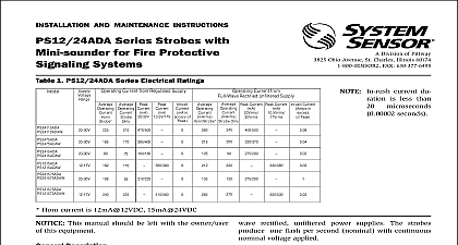
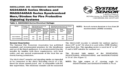
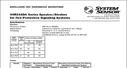
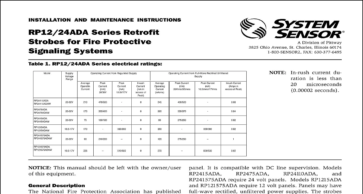
INSTALLATION AND MAINTENANCE INSTRUCTIONS Series Retrofit for Fire Protective Systems 1 RP12 24ADA Series electrical ratings Current from Regulated Supply Current from Full Wave Rectified Unfiltered in of Current Current Current in of Peak Division of Pittway 3825 Ohio Avenue St Charles Illinois 60174 FAX 630 377 6495 current du is less than microseconds seconds This manual should be left with the owner user this equipment Description National Fire Protection Association has published and recommended practices for the installation use of the listed appliances It is recommended that the be familiar with these requirements with local and any special requirements of the local fire au having jurisdiction RP12 24ADA series retroplates are ADA compliant 75 110 cd models signaling devices and designed for use existing or new installations They are a low cost alterna to replacing a sounder with a new sounder strobe signaling strobe is intended to be connected to the indicating circuit of a UL listed fire alarm control 1 Vertical and horizontal light distribution It is compatible with DC line supervision Models require 24 volt panels Models RP1215ADA RP121575ADA require 12 volt panels Panels may have rectified unfiltered power supplies The strobes one flash per second nominal with continuous voltage applied rated light output of the RP2415ADA RP1215ADA and RP121575ADA is 15 cd see Figure 1 rated light output of the RP2475ADA is 75 cd please Figure 1 rated light output of the RP24110ADA is 110 cd please Figure 1 The light output at 0 cid 176 viewing angle for RP12 models is 75 cd see Figure 1 Percent of Rating 0 25 90 45 75 50 55 55 45 60 40 65 35 70 35 75 30 80 30 85 25 90 25 All models can be powered using full wave recti unfiltered supplies Under no circumstances RP24ADA series devices input voltage exceed VDC or be less than 16 VDC 16 33Vrms for full rectified unfiltered supplies Under no cir can a RP12ADA series device input exceed 18.7 VDC or be less than 8.5 VDC 18.7Vrms for full wave rectified unfiltered The supply voltage rating of the horn musts be to or within the supply voltage rating of the General head screws are used to attach each device or of devices to the electrical outlet box See 2 and 3 for wiring methods Do not loop wires under the terminal screw Wires the device to the panel must be broken the device terminal connection in order to main electrical supervision strobe horn combination is designed for mounting ONLY boxes must be 4 square and at least 1 1 2 2 1 8 deep is recommended strobes must be mounted so that the top of the lens is 24 61cm below ceilings or as required by the authority jurisdiction Mounting Surface Mount See Figure 4 For the strobe to function properly the horn must be more than 1.9 deep see Figure 5 standard installations the strobe is mounted above horn see Figures 4 and 5 If the strobe is mounted the horn see page 4 for inverted mounting in procedures must conform to all applicable codes the requirements of the authority having jurisdiction Limitations of Sounder Strobes Sounder and or Strobe will not work without power The sounder gets its power from the fire security panel monitoring the alarm If power is cut off for any reason the sounder strobe will not pro the desired audio or visual warning Sounder may not be heard The loudness of the sounder meets or current Underwriters Laboratories standards However the may not alert a sound sleeper or one who has recently used drugs has been drinking alcoholic beverages The Sounder may not be heard it is placed on a different floor from the person in hazard or if placed too away to be heard over the ambient noise such as traffic air condition machinery or music appliances that may prevent alert persons from the alarm The Sounder may not be heard by persons who are impaired Signal Strobe may not be seen The electronic visual warning signal flashes at least once every three seconds meets or exceeds current Un Laboratories standard 1971 and uses an extremely reliable xe flash tube The visual warning signal is suitable for direct viewing and be installed within an area where it can be seen by building occu The strobe must not be installed in direct sunlight or areas of high intensity over 60 foot candles where the visual flash might be disre or not seen The strobe may not be seen by the visually im signal strobe may cause seizures Individuals who have a positive response to visual stimuli with seizures such as epileptics should prolonged exposure to environments in which strobe signals in this strobe are activated Sensor recommends that the Multi Alert Sounder and Signal always be used in combination so that the risks from any of the limitations are minimized signal strobe cannot operate from coded power supplies Coded supplies produce interrupted power The strobe must have an unin source of DC power in order to operate correctly Limited Warranty Sensor warrants its enclosed sounder strobe to be free from de in materials and workmanship under normal use and service for a of three years from date of manufacture System Sensor makes no express warranty for this sounder strobe No agent representative or employee of the Company has the authority to increase or alter obligations or limitations of this Warranty The Company obligation this Warranty shall be limited to the repair or replacement of any part of sounder strobe which is found to be defective in materials or work under normal use and service during the three year period com with the date of manufacture After phoning System Sensor toll number 800 SENSOR2 736 7672 for a Return Authorization number defective units postage prepaid to System Sensor Repair Depart RA 3825 Ohio Avenue St Charles IL 60174 Please a note describing the malfunction and suspected cause of failure Company shall not be obligated to repair or replace units which are to be defective because of damage unreasonable use modifica or alterations occurring after the date of manufacture In no case the Company be liable for any consequential or incidental damages breach of this or any other Warranty expressed or implied whatsoever if the loss or damage is caused by the Company negligence or fault states do not allow the exclusion or limitation of incidental or conse damages so the above limitation or exclusion may not apply to This Warranty gives you specific legal rights and you may also have rights which vary from state to state 2 Independent horn strobe wiring 3 Combination horn srtrobe wiring Next EOL VDC VDC VDC VDC BE Next EOL OUT OUT OUT OUT or Ty