System Sensor SA SP2R-2W-3R-3W12224MC

File Preview
Click below to download for free
Click below to download for free
File Data
| Name | system-sensor-sa-sp2r-2w-3r-3w12224mc-4076829531.pdf |
|---|---|
| Type | |
| Size | 812.04 KB |
| Downloads |
Text Preview
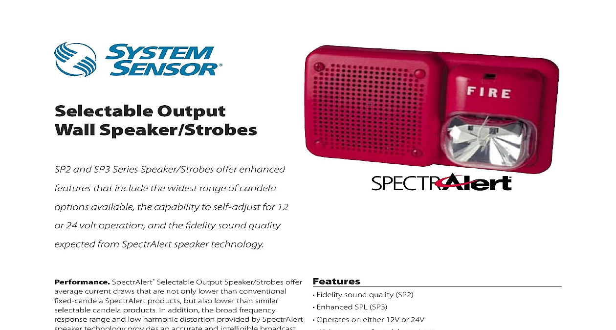
Selectable Output Speaker Strobes and SP3 Series Speaker Strobes offer enhanced that include the widest range of candela available the capability to self adjust for 12 24 volt operation and the fidelity sound quality from SpectrAlert speaker technology SpectrAlert Selectable Output Speaker Strobes offer current draws that are not only lower than conventional SpectrAlert products but also lower than similar candela products In addition the broad frequency range and low harmonic distortion provided by SpectrAlert technology provides an accurate and intelligible broadcast evacuation messages SpectrAlert Selectable Output Speaker Strobes offer a of installation friendly features such as the ability to mount to 4 4 21 back box without the need for an extension ring Also the field reversible strobe the speaker strobe may be either or right mounted to avoid potential obstructions SpectrAlert Selectable Output Speaker Strobes offer broadest range of candela options In addition the 15 cd and cd options can operate on either 12V or 24V with no setting the device recognizes the applied voltage and self adjusts the correct setting automatically The speaker voltage either 25.0 70.7 and power tap settings 1 or 2 watt are field selectable SpectrAlert Selectable Output Speaker Strobes the same stylish low profile design as the conventional products for a consistent and aesthetically pleasing across the entire product line sound quality SP2 SPL SP3 on either 12V or 24V range of candela options 15 and 15 75 candela options 15 15 75 30 75 and 110 candela options candela selection and 70.7 volt speaker with four field selectable power taps strobe for left or right mounting with MDL Sync Module Optional surface mount back box skirt available Listings Selectable Output Speaker Strobe Specifications Specifications shall be a System Sensor Model listed to UL 1480 and UL 1971 and be approved for fire protective signaling systems Speaker be capable of operating at 25.0 or 70.7 nominal Vrms and shall have a frequency range of 400 4000 Hz Speaker shall have power taps that are selected shunts The strobe shall consist of a xenon flash tube with associated lens reflector system and operate on either 12V or 24V The strobe shall also feature candela output providing options for 15 or 15 75 candela when operating on 12V and 15 15 75 30 75 or 110 when operating on 24V The strobe comply with the Americans with Disabilities Act requirement for visible signaling appliances flashing at 1 Hz over the strobe entire operating voltage range Specifications Operating Temperature Specifications Operating Voltage Terminals Voltage Range Voltage Range w Sync Module Specifications Voltage Terminals Range or 24 VDC and FWR unfiltered to 18 AWG 8 24V 16 9 24V 17 8 2 4 21 back box to 120 0 to 49 or 70.7 Vrms nominal to 18 AWG Hz SP2 and SP3 Series are UL listed from 400 to 4000Hz The SP2 Series will provide a flat from 100 to 15,000Hz The SP3 Series will provide a flat output from 500 to 13,000 Hz 1 and 2 watts 6,127,935 Watts Watt Watt Watt Taps Patent No Output UL Reverberant 10ft Strobe Feature the strobe screw and lifting the strobe assembly out of the rib slot the strobe to be rotated 180 and remounted to the base resulting in a strobe configuration SCREWDRIVER REMOVE of Published Strobe May 2004 Underwriters Laboratories changed standard UL 1971 to that operating current measurements are made using RMS root square instead of peak or average values RMS measurements more predict the power consumption of a device since they take into the entire current draw profile including surge repetitive surge and values The published RMS current is the maximum operating current of device within its operating voltage range This current maximum may or not occur at the endpoints of the voltage range May 2004 UL also changed the way they list the voltage range of a device 12V products will be listed between 8 and all 24V products will listed between 16 These devices are considered Any that does not operate within these ranges will be listed as a with its operating voltage specified on the device RIB Information Current Draw No Speaker Strobe back box skirt red back box skirt white Setting Max FWR Operating mA RMS Max DC Operating mA RMS Ohio Avenue St Charles IL 60174 800 SENSOR2 Fax 630 377 6495 System Sensor specifications subject to change without notice Visit systemsensor com for product information including the latest version of this data sheet 7 06 1676


