System Sensor SA SS2415ADAS

File Preview
Click below to download for free
Click below to download for free
File Data
| Name | system-sensor-sa-ss2415adas-0136985724.pdf |
|---|---|
| Type | |
| Size | 719.14 KB |
| Downloads |
Text Preview
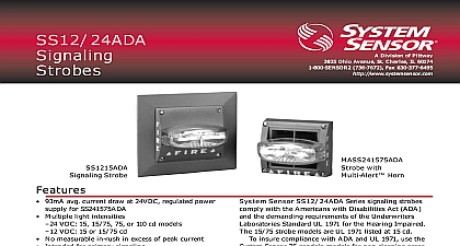
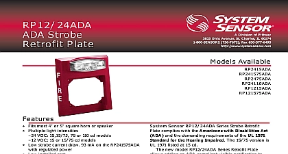
A Division of Pittway Ohio Avenue St Charles IL 60174 736 7672 Fax 630 377 6495 Available Strobe with Sync Strobe with Sync Sounder Strobe with Sync Sounder Strobe with Sync SS24ADAS Series Synchronized Strobes are crystal to flash at precisely one flash per second When is applied to an indicating circuit controlled by one all SS24ADAS or MASS24ADAS series devices in zone will flash simultaneously No synchronizing or coded supplies are necessary The strobes can used in any combination with other System Sensor strobes ADA horn strobes and ADA speaker unique lens reflector design maintains the UL 1971 dispersement pattern while flashing at the ADA 1 flash per second Available in red at 24 VDC SS24ADAS strobes can be surface mounted directly to standard 4 backbox or can be mounted to our semi plate for recessed electrical boxes They are also in combination with System Sensor Multi Alert for both visible and audible signaling Strobes Sync Works on two wire circuit No synchronization module required Synchronized and unsynchronized strobes can be on the same zone in any combination Patent pending Sync 24 VDC versions only 15 and 15 75 cd versions available Available with Multi Alert Sounder Constant current draw over voltage range Stand alone strobe mounts to single gang box with plate ADA compliant UL 1971 listed Installer easy plug in terminal strip stand alone strobe terminals Weight Strobes 12 AWG oz 141g oz 293g 4 11 2 standard backbox recommended 4 11 2 standard backbox recommended with semiflush mounting plate separately Range F to 120 cid 176 F 0 cid 176 C to 49 cid 176 C Series ADA Series ADA System Sensor 8 96 document is not intended to be used for installation purposes Description Series SS24ADAS strobes are suitable for primary in public mode life safety applications The can be connected to the alarm indicating circuit of UL listed fire alarm control panel They are compatible DC line supervision Panels may have full wave unfiltered power supplies The strobes are for 24VDC operation and can be used with the Sensor Multi Alert horn Stand alone strobe incorporate these easy features plug Output Selection Guide terminal strip wiring guide and strip gauge on back mounting is available with the addition of an accessory plate When installed in a zone the and MASS24ADAS Series devices flash Note SS24ADAS and MASS24ADAS devices operating in the same zone will not be if energized at different times i e if than one controller is controlling the same zone Sounder MA12 24D mA Output dBA Regulated FWR Unfiltered2 dBA Ratings Sounds Whoop Hz continuous factory setting Hz Alternating Interrupted Continuous Interrupted Frequency Warble on ABC 1 Sounder MA12 24EH mA Output dBA on Regulated FWR Unfiltered2 dBA Ratings ABC 1 Sounds Whoop Hz Continuous Hz Fast Dual Hz Continuous factory setting dBA measured in anechoic room at 10 feet The acoustical output shall meet the current requirements of UL Standard 464 See Tone Selection diagram below for tab clip removal and storage All models can be powered using uncoded full wave rectified unfiltered supplies Under no circumstances can SSADAS or MASSADAS input voltage exceed 33 VDC or be Sounder Tone Selection than 20 VDC SLOT C C S TABS A B C 2 STORING UNUSED CLIPS COVER BACK TO ALIGN COVER SLOT CLIP STORAGE POST A SMALL BLADED SCREWDRIVER TO REMOVE CLIPS REMOVED OR TO SELECT TONE Light Distribution Dispersion AXIS of Rating Dispersion of Rating 5 25 30 45 polar light distribution in both horizontal and vertical directions is mandated for the strobes by the Standard UL 1971 for the Hearing Impaired with minimum intensity percentages as shown in the graphs above VDC VDC or Only Independent Next EOL VDC VDC VDC VDC BE or off tab VDC VDC or included in screw pack must be as shown for tandem operation Combination 5 30 Next EOL Next EOL Strobe Mount Mount Strobe Mount Mount 3 Strobe Strobe Ratings Strobe Only Range Regulated mA Operating mA Operating Current Current from Wave Rectified Supply mArms For additional information see installation manual D900 06 00 for EH models see installation manual D900 12 00 Specifications shall be a System Sensor Model listed to UL 1971 for the Hearing Impaired and shall be for Fire Protective Service Strobe shall be wired a Primary Signaling Notification appliance Strobe shall comply with the Americans with Disabilities Act for visible signaling appliances Strobe shall at 24VDC from a regulated DC supply or full wave unfiltered supply The signaling strobe shall be from a non coded power supply when powered the horn or powered independently Visual signaling are to be installed in all non sleeping corridor and areas 110 cd only per plans and specifications strobe light shall consist of a xenon flash tube and Information lens reflector system Each strobe shall be for one flash per second over all operating All strobes shall be capable of mounting to a 4 4 11 2 backbox in either a surface mount semiflush mount with separate mounting plate Strobe flash synchronously with other SS24ADAS and Series devices in the same zone for a of 15 minutes Note SS24ADAS and MAEH24ADAS Series devices in the same zone will not be synchronized if at different times i e if